Install lift-assist, Install wheels, Dismount spindles – Great Plains YP625PD Predelivery Manual User Manual
Page 37: Assemble wheels, Dismount spindles assemble wheels
Great Plains Manufacturing, Inc.
Planter Assembly
33
07/05/2011
401-754Q
Install Lift-Assist
If the planter is a pull-type implement, continue at “Install
Tongue” on page 39.
Install Wheels
Refer to Figure 65
Note: Use the caster pivot locks
as needed to prevent
caster swiveling.
Note: The pivot arm
is shown hoisted. The work can
be performed with the arm resting on the ground.
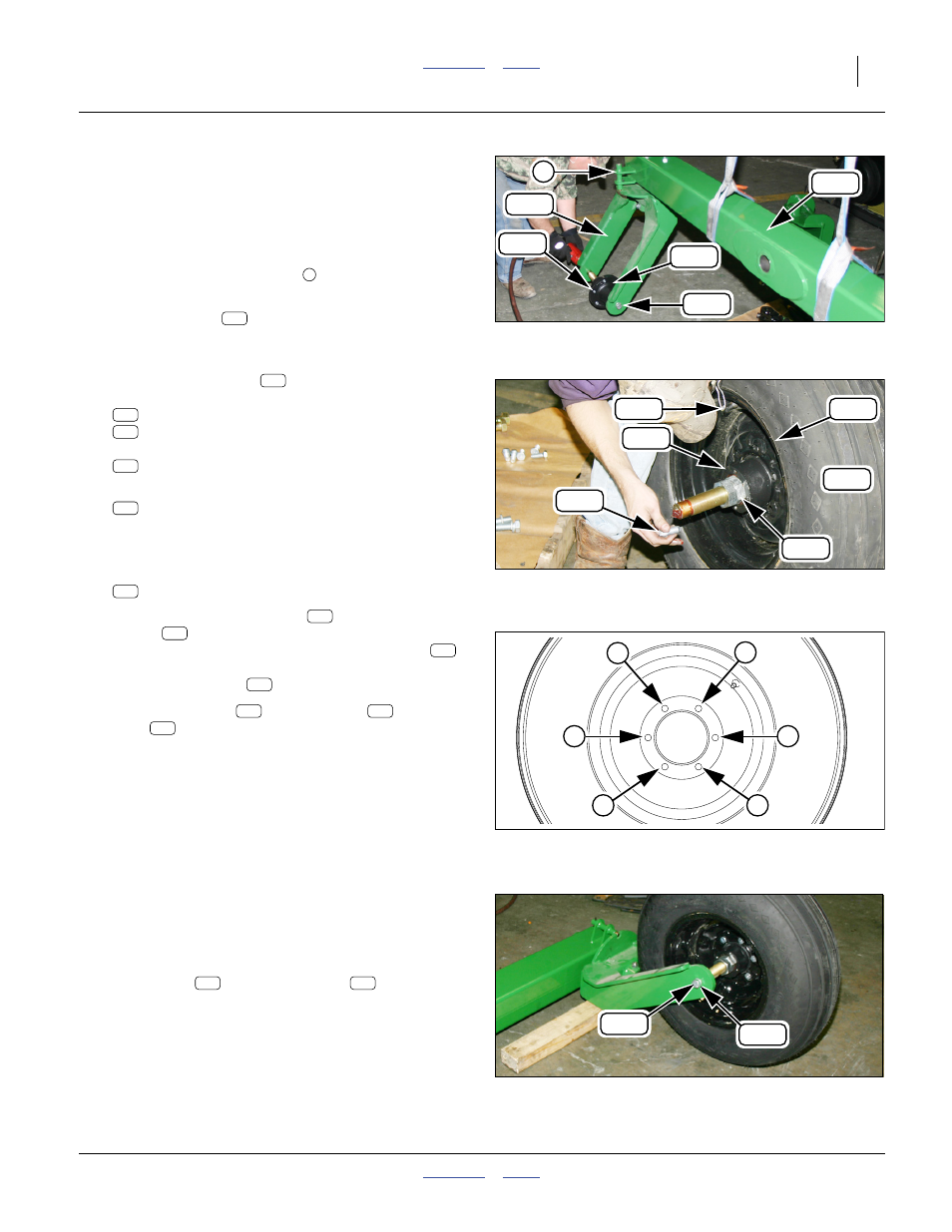
Dismount Spindles
130. At each caster frame
, remove and save two
sets:
802-065C HHCS 3/4-10X2 1/4 GR5
804-023C WASHER LOCK SPRING 3/4 PLT
and then remove the spindle:
815-200C HUB ASSY 6BOLT 6"BC 4.62PILOT
131. At each spindle, remove and save six:
802-845C BOLT WHL 9/16-18X1 1/8 GR5
Assemble Wheels
Refer to Figure 66
132. Select one:
161-046K 6 BOLT WHL&TIRE 8 PLY TUBELESS
Note: The “outside” of the wheel
has the valve
stem
. The bolt holes are raised to the outside,
and counter-sunk for the self-centering bolts
.
The “outside” of the spindle is the threaded end
with two jam nuts
.
133. Insert the spindle
into the wheel
. Insert
bolts
to finger-tight.
Refer to Figure 67
134. Following the order in the bolt torquing pattern,
gradually tighten the bolts to Grade 5 specification.
Refer to Figure 67 (which depicts the caster frame to the front
of the caster arm)
135. Align the wheel/spindle assemblies in the caster
frames. Orient the wheels with the valve stems to
the outside (which is toward the inside is the caster
frames are reversed, as in the figure). Secure with
saved bolts
and lock washers
.
Null4:
Figure 65
Dismount Spindle
Q0052
154
360
110
7
262
282
154
Null4:
Figure 66
Assemble Wheel
Q0053
115
301
282
358
360
361
110
262
314
360
282
115
Null4:
Figure 67
Bolt Torquing Pattern
32065
4
6
1
3
5
2
358
361
282
301
282
358
360
Null4:
Figure 68
Mount Wheel
Q0054
262
314
262
314