Place right shaft, Closeout shafts, Place right shaft closeout shafts – Great Plains YP625PD Predelivery Manual User Manual
Page 36: Step 129
32
Great Plains Manufacturing, Inc.
YP625PD/TD/925TD
401-754Q
07/05/2011
Place Right Shaft
118. Select one of the shafts from the table at right,
based on planter model
119. Start at the right end opener mount.
Refer to Figure 61
120. For the next mount to the left, lift the meter drive
idler spring
off one of its anchor pins. This
provides chain slack for the next steps.
121. Select one:
808-395C SPKT 41C12 W/SS SPCL PLT
Back out the set screws until the hex bore is clear.
Determine the sprocket orientation required for the
next opener mount to the left. Hold the sprocket in
that orientation. Loop the meter chain around it.
Refer to Figure 62
122. Hold the sprocket (with chain) in position against the
mount bearing. Leave set screws accessible (for
tightening at step 129). Insert the shaft. Stop shaft
insertion just before the next mount to the left.
123. At the mount just completed, re-connect the idler
spring.
124. Repeat step 120 through step 123 for the remaining
mounts on the right side of the planter.
Closeout Shafts
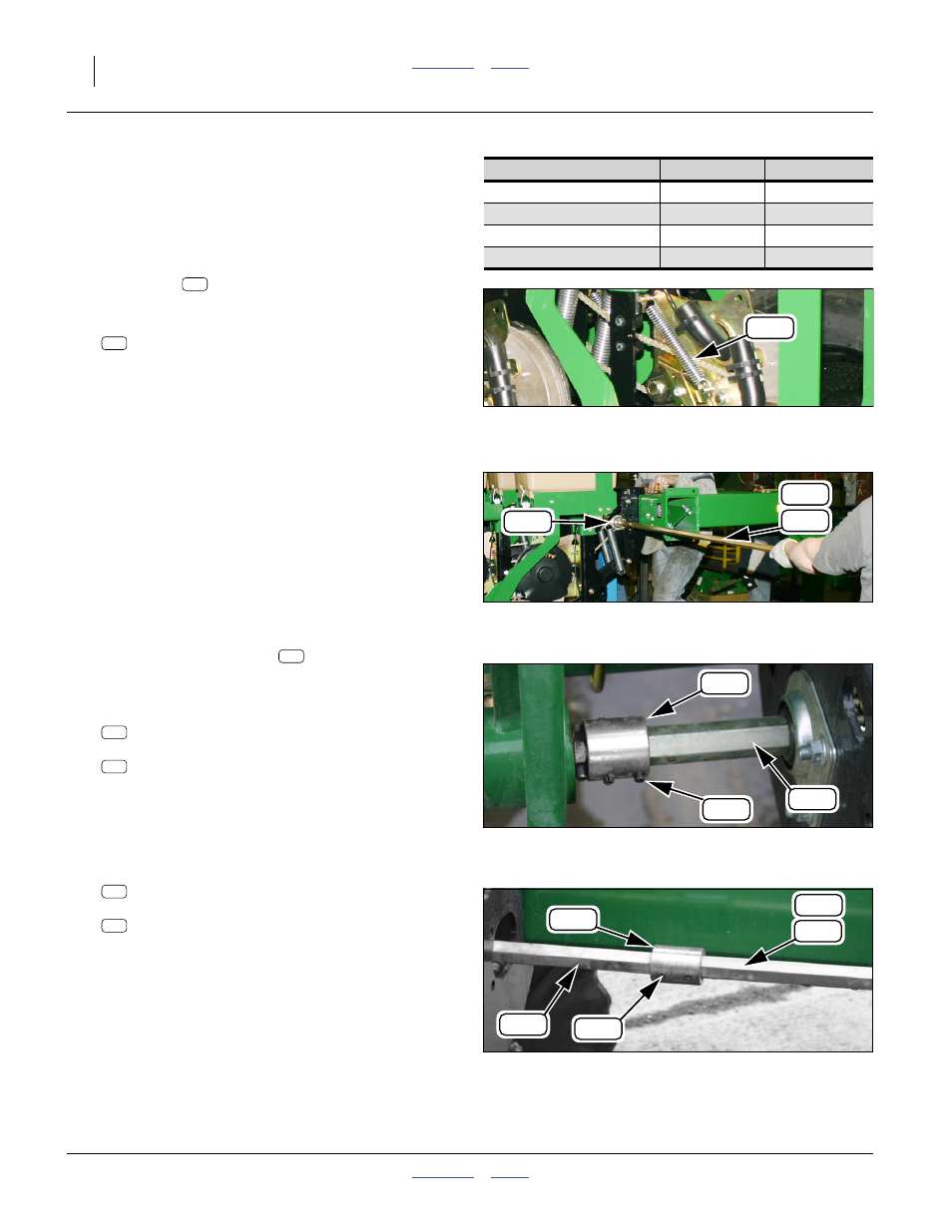
Refer to Figure 63
125. Rotate the left drive shaft
to align the pin hole
with the pin hole in the transmission output shaft
(not visible in figure).
126. Select one:
402-076D COUPLER, SHEAR OUTPUT
and two:
805-428C PIN SPIROL 1/4X2
HEAVY PLN
Place the coupler on the transmission output shaft.
Secure with roll pin. Slide the left drive shaft into the
coupler. Secure with roll pin.
127. Rotate the left or right shafts to align the pin holes.
128. Select one:
402-076D COUPLER, SHEAR OUTPUT
and two:
805-428C PIN SPIROL 1/4X2
HEAVY PLN
Place the coupler on the right end of the left shaft.
Secure with roll pin. Slide the tight drive shaft into
the coupler. Secure with roll pin.
129. Slide all sprockets into contact with mount bearings.
Tighten all set screws.
Null4:
Null4:
Figure 61
Meter Drive Idler Spring
Q0049
347
Model
Part
Length
402-637D
322.6 cm
402-637D
322.6 cm
402-637D
322.6 cm
402-636D
241.3 cm
347
350
Null4:
Figure 62
Right Shaft Insertion
Q0048
183
382
182
Null4:
Figure 63
Left Shaft at Transmission
Q0050
166
337
181
181
166
337
Null4:
Figure 64
Left and Right Shafts Coupled
Q0051
166
337
181
182
183
166
337