Setup parallel arms – Great Plains YP625PD Predelivery Manual User Manual
Page 32
28
Great Plains Manufacturing, Inc.
YP625PD/TD/925TD
401-754Q
07/05/2011
Setup Parallel Arms
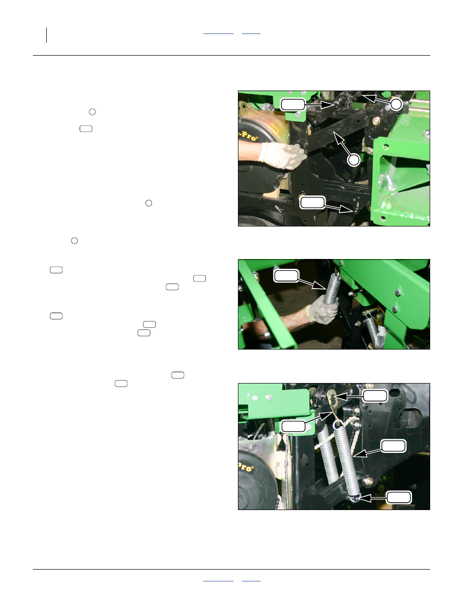
Refer to Figure 49, Figure 50 and Figure 51
Row units pre-installed on the main frame may have
shipping braces
to provide clearance from other
planters in shipment. If braces are installed, parallel
arms springs
are also removed for shipment.
If no openers are pre-installed, or all installed openers
have springs, and no braces, continue at “Mount
Openers” on page 29.
For each pre-installed row unit:
95. Support the weight of the row unit opener (at some
point to the rear of the parallel arms).
96. Set the spring adjuster cam
(See Operator manual for settings.
Figure 49 shows position one).
97. Remove the fasteners that secure the shipping
brace
. Remove the brace. Lower the opener.
The brace and fasteners are not re-used.
98. Select two:
198-240D 3 13/32 SPRING STRAP
Hook the large “keyhole” end of the straps
onto
each end of the spring anchor pin
in the upper
parallel arm weldment.
99. Select two:
807-076C SPRING EXT 1.575 OD X .225 W
Hook one end of the spring
through the smaller
(bottom) hole of the strap
.
Note: With the row unit fully lowered on the parallel arms,
it is possible to make the next attachment by hand.
Wear gloves.
100. Hook the bottom end of the springs
onto the
spring anchor pins
of the bottom parallel arm
casting.
Null4:
Null4:
Figure 49
Opener Brace
Q0042
1
2
144
199
346
2
Null4:
Figure 50
Attach Spring
Q0043
346
120
120
144
346
346
120
Null4:
Figure 51
Springs Attached
Q0044
120
144
199
346
346
199