Connect air sensor lines, Connect ambient air line, Connect gauge line – Great Plains YP625PD Predelivery Manual User Manual
Page 77: Connect ambient air line connect gauge line
Great Plains Manufacturing, Inc.
Planter Assembly
73
07/05/2011
401-754Q
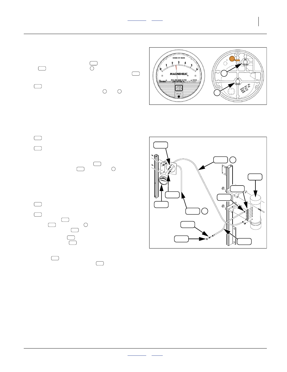
Connect Air Sensor Lines
Refer to Figure 145 (on page 73) and Figure 146
Lines from the sensor chamber
to the pressure
gauge
, and to meter ports (
in Figure 147), are
made by cutting lengths from a supplied coil of hose
.
325. Select two:
830-276C AD 1/8MNPT X 1/4HB BRASS
Thread these into the rear ports (
and
) of the
pressure gauge. Do not use pipe sealant; it is not
necessary and may foul the gauge.
Null4:
Connect Ambient Air Line
326. Select one:
800-395C CLAMP SPRING BAND 1/2 OD HOSE
and the coil of:
990-021R HOSE 1/4 RUBBER AIR
Cut a length of:
40 to 60 cm
from the coil. Use the clamp
to connect this
short length of hose
to the lower
[“low pressure” / ambient air] gauge port. Route the
hose down the mount and tie it to the mount so that
the open end is facing down.
Connect Gauge Line
327. Select two:
800-395C CLAMP SPRING BAND 1/2 OD HOSE
and the coil of:
990-021R HOSE 1/4 RUBBER AIR
Use a clamp
to connect one end of the
tubing
to the upper
[“high pressure” / sense]
port of the gauge
.
328. Route the hose
along tool bars and ribs to the
sensor chamber
. Secure the hose along the
route with cable ties. Do not pull the ties too tight.
Remove any protective cap on the bottom brass
adaptor
on the chamber. Cut the hose to
length. Place the other clamp
on the hose.
Secure the hose to the chamber adaptor.
Null4:
Null4: .
Figure 145
Pressure Gauge Ports
29842
1
2
186
402
3
403
383
1
2
Null4: .
Figure 146
Connect Sense Lines
29951
403
2
403
402
1
186
250
250
383
383
403
383
305
250
403
250
403
2
250
403
250
403
1
402
403
186
383
250