Install fertilizer jackshaft and shaft – Great Plains YP625PD Predelivery Manual User Manual
Page 26
22
Great Plains Manufacturing, Inc.
YP625PD/TD/925TD
401-754Q
07/05/2011
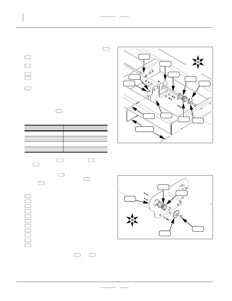
Install Fertilizer Jackshaft and Shaft
Refer to Figure 38
59. Select the fertilizer jackshaft bracket assembly
,
which may have been removed at step 6:
407-657D FERT HOPPER JACKSHAFT MNT BRKT
It includes the following fasteners:
806-073C U-BOLT 3/8-16 X 7 1/32 X 7 7/8
with two sets:
804-013C WASHER LOCK SPRING 3/8 PLT
803-014C NUT HEX 3/8-16 PLT
60. Select also the jackshaft itself:
407-660D DRY FERTILIZER JACK SHAFT
which may have been removed for shipping even if
the bracket is installed. This shaft may have been
dismounted prior to shipping by removing a pin, a
collar, a coupler or flangettes.
61. Mount the bracket
on the rear face of the front
tool bar, slotted end up, at the following distance
from the left end of the frame:
Secure with U-bolt
, lock washers
and
nuts
.
Refer to Figure 38 and Figure 39
62. Install the jackshaft
from the fertilizer
transmission plate (“fertilizer case”
) to the
bracket
.
From left to right, the ordering of parts is:
Leave fasteners at flangettes
and
only fin-
ger-tight. Shaft alignment is adjusted at step 219 on
page 50.
Null4:
Planter Model
Bracket Offset
44.4 cm
28.3 cm
a.
805-126C PIN LINCH 1/4 X 1 3/4 PLT
b.
808-150C SPKT 40C23 X 7/8 HEX BORE
c.
805-180C PIN ROLL 1/4 X 1 1/2 LG PLT
d.
822-032C FLANGETTE 52 MST
822-119C BRG 7/8HEXX2.05OD SPH
e.
407-308D FERTILIZER CASE
f.
402-058D COLLAR LOCK 7/8 HEX
g.
822-175C FLANGETTE 52 3-BOLT PLT
822-119C BRG 7/8HEXX2.05OD SPH
h.
407-147D ADJUSTABLE SHAFT SUPPORT
i.
407-073D COUPLER, DRY FERT
(this part may be on a hopper assembly)
Null4:
Figure 38
Fertilizer Jackshaft Bracket
31841
See Table
381
165
U
D
F
B
L
R
380
209
208
333
285
309
340
227
229
227
227
340
309
285
229
227
340
309
285
Null4:
Figure 39
Fertilizer Jackshaft
31841
379
329
U
D
F
B
L
R
348
380
213
229
213
227
329
348
333
379
380
213
165
381
380
209
208
379
381