About shafts and sprockets, Place left shaft, About shafts and sprockets place left shaft – Great Plains YP625PD Predelivery Manual User Manual
Page 35: Bf l r
Great Plains Manufacturing, Inc.
Planter Assembly
31
07/05/2011
401-754Q
About Shafts and Sprockets
Shaft and sprocket installation must be done in a specific
order, or there will be substantial re-work, or chain
damage in field use.
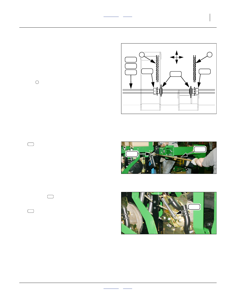
Refer to Figure 58, a top view of two openers
• Shafts are inserted into opener mounts and bearings
from the right side of the planter, left shaft first.
• Unless the shaft will pass entirely through the opener
mount during insertion, sprockets, with meter drive
chains
around them, are placed on the shaft as it
passes through the mount.
• Sprockets must be on a specific side of the bearing,
and with the lock collar side of the sprocket away from
the bearing:
Short mount: sprocket on left side of bearing
Mid mount: sprocket on right side of bearing
Long mount: sprocket on left side of bearing
• Drawings on page 82 through page 94 show sprocket
placement and orientation for each planter model.
Place Left Shaft
Refer to Figure 59
111. Select one 303.5 cm hex shaft:
402-635D SHAFT METER DRIVE YP625 T
This shaft is the left shaft for all planter models
covered by this manual.
Note: No sprocket placement is required on the right side
of the planter for the left shaft.
112. Insert the shaft through all the mount bearings on
the right half of the planter. Stop insertion just to the
right of the mount that is at center, or just left of
center if there is no center mount.
Refer to Figure 60
113. For the next mount to the left, lift the meter drive
idler spring
off one of its anchor pins. This
provides chain slack for the next steps.
114. Select one:
808-395C SPKT 41C12 W/SS SPCL PLT
Back out the set screws until the hex bore is clear.
Determine the sprocket orientation required for the
next opener mount to the left. Hold the sprocket in
that orientation. Loop the meter chain around it.
115. Hold the sprocket (with chain) in position against the
mount bearing. Leave set screws accessible (for
tightening at step 129 on page 32). Insert the shaft.
Stop shaft insertion just before the next mount to
the left.
116. At the mount just completed, re-connect the idler
spring.
117. Repeat step 113 through step 116 for the remaining
mounts on the left side of the planter.
Null4:
Figure 58
Sprocket Orientation
Q0046
B
F
L
R
350
350
382
Short
Mid or
Long
2
181
182
183
Null4:
Figure 59
Left Shaft Insertion
Q0048
181
382
181
Null4:
Figure 60
Meter Drive Idler Spring
Q0049
347
347
350