Point gauge wheel adjustment, Yoke spring length, Install gauge wheels – Great Plains YP625PD Predelivery Manual User Manual
Page 28: Step 67
24
Great Plains Manufacturing, Inc.
YP625PD/TD/925TD
401-754Q
07/05/2011
3-Point Gauge Wheel Adjustment
If this is a pull-type planter, continue “Pull-Type Gauge
Wheel Adjustment” on page 23.
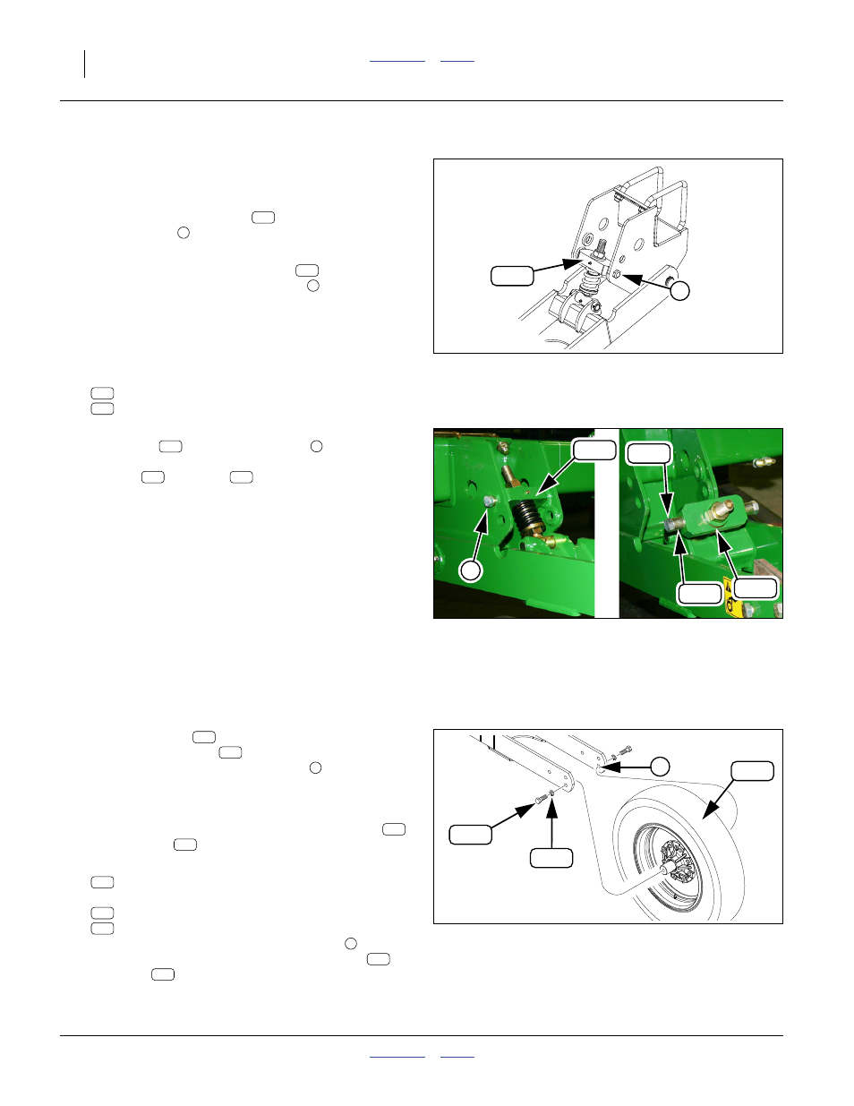
Refer to Figure 41 and Figure 42
If all of the gauge wheel yokes
are bolted into the
lower mount holes
For shipment, the gauge wheel yokes
) may be in
flat-ground position (upper mount holes
, as depicted
in left panel of Figure 42) or detached entirely (right
panel of Figure 42).
Note: Prepare to support the gauge wheel arm before
removing bolts.
67. Remove and save two sets:
802-064C HHCS 3/4-10X2 GR5
402-586D SLEEVE SPRING LINK MOUNT
68. Adjust the arm position to allow alignment of the
yoke block
with the lower holes
of the mount.
Secure the yoke in that position with the
sleeves
and bolts
.
Yoke Spring Length
69. Check the length of the spring. See “Gauge Wheel
Adjustments” in the 401-754M or 401-755M
Operator manual.
Null4:
Install Gauge Wheels
Refer to Figure 43
70. If gauge wheels
are already installed, check
where the axle bolts
are installed in the arm
holes. If they are in the lower holes
planting configuration), continue at step 72 on
page 25.
If installed in the upper holes, remove the bolts
and washers
, and continue at step 71.
71. At each gauge wheel arm, select one:
814-385C TIRE & WHL ASY 8R19.5LT
and two sets:
802-065C HHCS 3/4-10X2 1/4 GR5
804-023C WASHER LOCK SPRING 3/4 PLT
Align the wheel axle with the lower holes
gauge wheel arm. Secure with lock washers
and bolts
.
Null4:
Null4:
Figure 41
Yoke in Field Position
31942
1
169
169
169
2
261
180
Null4:
Figure 42:
Shipment Configurations
Q0029
169
180
261
169
2
169
180
261
Null4:
Figure 43
Gauge Wheel Installation
29994
3
262
314
359
359
261
262
314
359
262
314
3
314
262