Install center hopper, Install right hopper, Install center hopper install right hopper – Great Plains YP625PD Predelivery Manual User Manual
Page 55
Great Plains Manufacturing, Inc.
Planter Assembly
51
07/05/2011
401-754Q
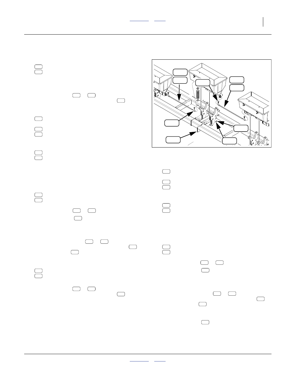
Install Center Hopper
Refer to Figure 104
222. Select one of (per table on page 50):
407-560L 4-OUTLET DRY FERT HOPPER ASSY
407-561L 3-OUTLET DRY FERT HOPPER ASSY
If the planter is a pull-type, select the hopper
modified per step 209 - step 213 on page 49. Attach
hoist lines.
223. Hoist the hopper (
or
) to the center of the
front tool bar, with the meter drop lines
behind
the tool bar.
224. Select two:
806-052C U-BOLT 5/8-11 X 7 1/32 X 8 1/2
and four sets:
804-022C WASHER LOCK SPRING 5/8 PLT
803-021C NUT HEX 5/8-11 PLT
Loosely secure the hopper assembly to the tool bar.
225. Select one of (per table on page 50):
407-659D 9-ROW DRY FERT HPR CPLR SHAFT
407-661D FERT HOPPER CPLR SHAFT 41.5
226. With the coupler shaft held between the two hopper
shaft ends, adjust the center hopper position on the
tool bar for a shaft-to-shaft gap of:
5 mm (
3
⁄
16
in).
227. Select two sets:
407-073D COUPLER, DRY FERT
805-065C PIN WIRE RETAINING 1/4 X 1 3/4
These may be located on the hopper shafts, or on
the coupler shaft (
or
).
228. Place one coupler
on the right end of the left
hopper shaft, and on the left end of the center hop-
per shaft, with the pin hole closer to the end of the
coupler that is away from the hopper.
229. Bring the coupler shaft (
or
) into alignment
with the hopper shafts. Engage the couplers
.
Secure with pins
.
Install Right Hopper
230. Select one of (per table on page 50):
407-560L 4-OUTLET DRY FERT HOPPER ASSY
407-561L 3-OUTLET DRY FERT HOPPER ASSY
Attach hoist lines.
231. Hoist the hopper (
or
) to the right of the
front tool bar, with the meter drop lines
behind
the tool bar. The position is as far from center-line
as the left hopper is from center-line.
232. Select two:
806-052C U-BOLT 5/8-11 X 7 1/32 X 8 1/2
and four sets:
804-022C WASHER LOCK SPRING 5/8 PLT
803-021C NUT HEX 5/8-11 PLT
Loosely secure the hopper assembly to the tool bar.
233. Select one of (per table on page 50):
407-659D 9-ROW DRY FERT HPR CPLR SHAFT
407-661D FERT HOPPER CPLR SHAFT 41.5
234. With the coupler shaft held between the two hopper
shaft ends, adjust the right hopper position on the
tool bar for a shaft-to-shaft gap of:
5 mm (
3
⁄
16
in).
235. Select two sets:
407-073D COUPLER, DRY FERT
805-065C PIN WIRE RETAINING 1/4 X 1 3/4
These may be located on the hopper shafts, or on
the coupler shaft (
or
).
236. Place one coupler
on the right end of the center
hopper shaft, and on the left end of the right hopper
shaft, with the pin hole closer to the end of the cou-
pler that is away from the hopper.
237. Bring the coupler shaft (
or
) into alignment
with the hopper shafts. Engage the couplers
.
Secure with pins
.
238. Engage all couplers. Disengage fertilizer transmis-
sion chain. Verify that the fertilizer shafts turn freely.
Secure all U-bolts
.
Null4.aac:
Null4:
Figure 104
Center Hopper
31882
313
325
208
287
228
230
339
230
228
216
217
216
217
362
339
313
287
228
230
208
325
228
230
208
228
230
208
325
216
217
216
217
362
339
313
287
228
230
208
325
228
230
208
228
230
208
325
339