Connect ground drive spring, Install lift assist weldment – Great Plains YP625PD Predelivery Manual User Manual
Page 31
Great Plains Manufacturing, Inc.
Planter Assembly
27
07/05/2011
401-754Q
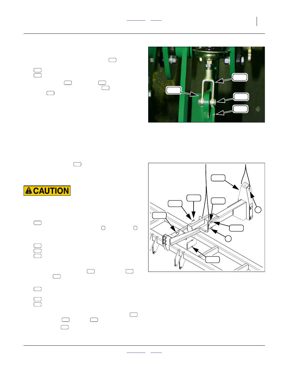
Connect Ground Drive Spring
Refer to Figure 47
89. At the ground drive arm spring yoke
, remove
and save:
805-064C PIN COTTER 7/64 X 1 LONG
805-127C PIN CLEVIS 1/2 X 1 3/4
90. Align the yoke
with the lug
on the ground
drive arm. Secure with clevis pin
and
cotter
.
Install Lift Assist Weldment
If the planter is a pull-type model, continue at “Mount
Openers” on page 29.
Refer to Figure 48
The lift-assist weldment
must be installed prior to
installing components that would otherwise interfere with
installation of this weldment. The axle, casters and
hydraulics are not installed until page 33.
Pinch and Crush Hazard:
Use two lift lines. Maneuver the weldment carefully. The
weldment weighs over 300 kg.
91. Select one:
401-751H LIFT ASSIST MOUNT WELD
Secure hoist lines at the forward
and top rear
holes.
92. Select four sets:
802-055C HHCS 5/8-11X2 GR5
804-022C WASHER LOCK SPRING 5/8 PLT
803-021C NUT HEX 5/8-11 PLT
Bring the forward plate of the lift-assist weldment
into contact with the mid plate of the main frame.
Loosely secure with bolts
, lock washers
and nuts
.
93. Select two:
806-050C U-BOLT 3/4-10 X 7 X 8 1/2
and four sets:
804-023C WASHER LOCK SPRING 3/4 PLT
803-027C NUT HEX 3/4-10 PLT
Secure the mid plate of the lift-assist weldment to
the rear tool bar of the main frame with U-bolts
,
lock washers
and nuts
; Grade 5 torque.
94. Secure bolts
at forward plates.
Null4:
Null4:
Figure 47
Ground Drive Spring
Q0033
330
106
324
170
106
324
330
106
170
330
324
Null4:
Figure 48
Lift-Assist Weldment
32053
7
155
338
291
314
313
287
259
8
155
155
259
313
287
259
313
287
338
314
291
338
314
291
259