Install drive shaft – Great Plains YP625PD Predelivery Manual User Manual
Page 34
30
Great Plains Manufacturing, Inc.
YP625PD/TD/925TD
401-754Q
07/05/2011
Install Drive Shaft
Component Damage Risk:
Use two workers to remove the shaft from the tube. Place the
removed shaft on a long flat surface or level supports. Avoid
bending the shafts or stressing the coupler connecting them.
104. Open cap
at right end of main tool bar. Have
two people remove the drive shaft assembly
from the tool bar.
105. Re-attach the cap to the end of tool bar and secure
it with fasteners provided.
106. Secure the fasteners of the cap at the other end of
the tool bar.
Refer to Figure 56 and Figure 57
The drive shaft is in two sections:
(
and
, or
and
),
held together at a coupling
with pins
partially
inserted. The meter driving sprockets
are shipped
on this shaft, and may held in place with their own set
screws, or by lock collars
.
107. Remove and save the pins and the coupler that join
the shafts:
805-428C PIN SPIROL 1/4X2
HEAVY PLN
402-076D COUPLER, SHEAR OUTPUT
108. A second coupler is required for connecting the
shafts to the output of the meter drive transmission.
Locate this coupler and its pins. It may be on the
shafts, installed at the transmission, or in a carton.
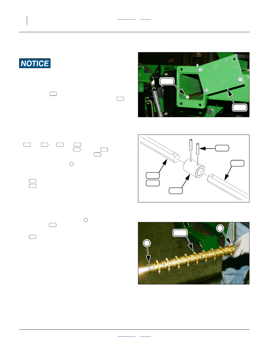
Refer to Figure 57
109. Remove any locking collars
that retain
sprockets
on shaft. The collars are not re-used.
110. Remove and save all sprockets:
808-395C SPKT 41C12 W/SS SPCL PLT
Null4:
Figure 55
Remove Drive Shaft
Q0045
145
181
145
181
Null4:
Figure 56
Shaft Coupling Detail
32054
337
166
181
182
183
181
182
181
183
166
337
350
1
337
166
Null4:
Figure 57
Sprockets on Drive Shaft
Q0041
350
1
1
1
350
350