ClearOne Converge 590 User Manual
Page 8
8
Technical Services: 800.283.5936
MIXER (FRONT)
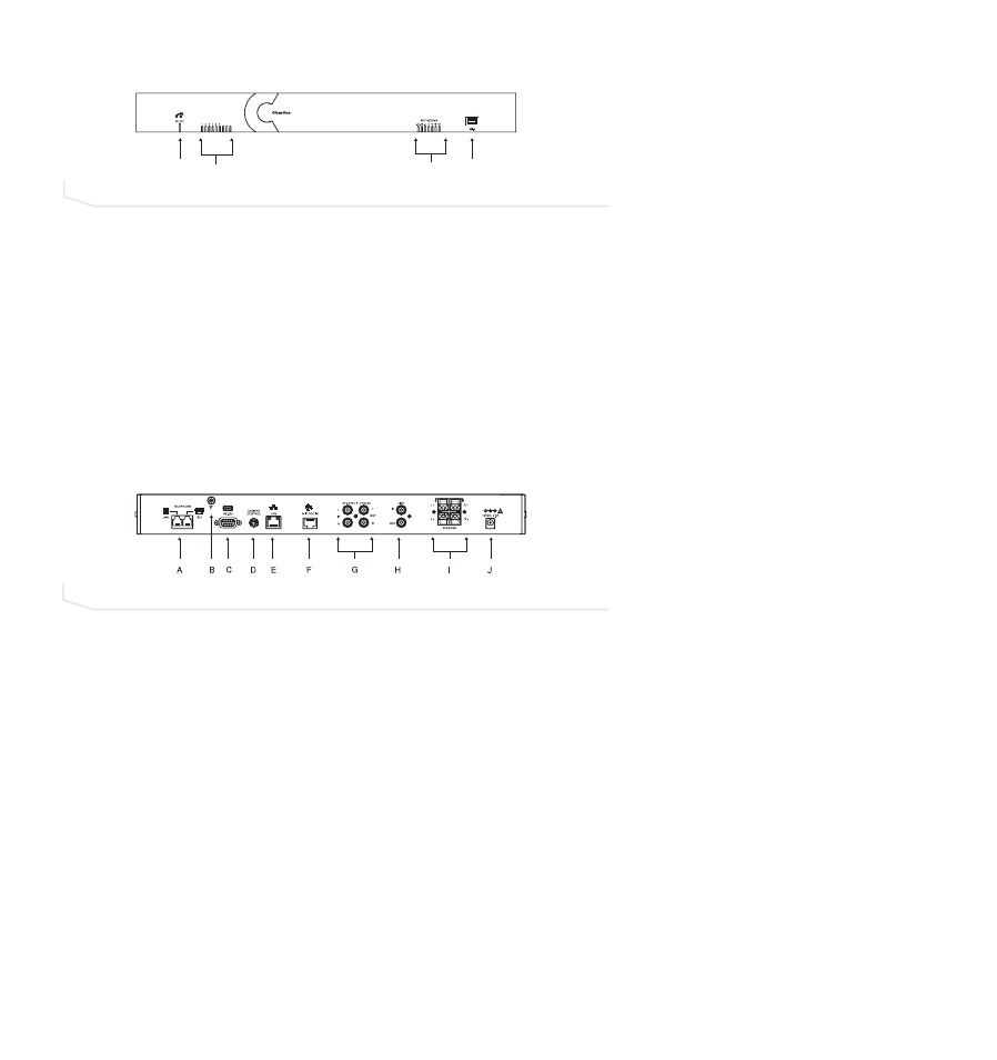
A. Telephone LLED. This indicator lights red when the Converge is powered, but the telco
is on hook (not in use). The indicator lights green when the telco is off hook (in use)
and flashes green during an incoming call.
B. Microphone sstatus LLEDs. Nine indicators (Converge 590) or six indicators (Converge
560) indicate the activation status of the mic elements. When a mic element is gated,
the corresponding LED lights green. When mics are muted, the LEDs for the corre-
sponding mics turn red.
C. Meter LLEDs. These LEDs represents audio from all inputs.
D. USB pport. This port enables USB connection to a PC.
MIXER (BACK)
A. Telephone S
Set, LLine. RJ-11 connection to an analog telephone jack and an analog
telephone set.
B. RF aantenna cconnector ((RF ccontroller). Connect the external RF antenna to this port.
C. RS-2232. RS-232 control port for connection to a control system such as AMX or
Crestron or to a computer.
D. Camera C
Control. VISCA camera control port. This connection enables microphone
activation to trigger camera presets (voice tracking).
E. LAN. This is a 10/100 BaseT auto-detecting Ethernet port for system control through a
data network.
F. Mic P
Pod IIn. Use a Cat. 5 cable with RJ-45 connectors to connect the microphone
breakout boxes.
G. Playback IIn/Record O
Out. RCA connection to record/playback devices such as a VCR.
H. Line IIn/Out. RCA connection to a codec, amplifier or sound card.
I.
Speaker O
Output. Use speaker wire to connect these push terminals to the speakers.
J. Power 112 VVDC. Power supply.
FIGURE 1.4
Converge mixer (front)
ANTENNA
FIGURE 1.5
Converge mixer (back)