Side view (enlarged) front view – Rockwell Automation GV3000/SE AC Drive AutoMax Network Communication Board, M/N 2AX3000 User Manual
Page 39
2-30
AutoMax Network Communication Option Board for the GV3000/SE AC Drive
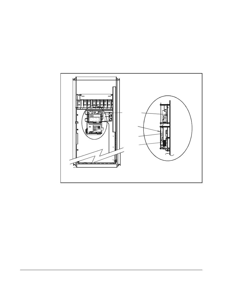
Step 2.5 Ensure that the DC bus capacitors are discharged. To check
DC bus potential:
a. Stand on a non-conductive surface and wear insulated gloves. (600 V)
b. Use a voltmeter to check the DC bus potential at the Voltmeter Test
Points on the Power Module Interface board. See figure 2.16.
Step 3.
Remove the Keypad Bracket from the Drive
Refer to figure 2.16 for component locations.
Step 3.1 Record connections to the Regulator board terminal strip if they must be
disconnected to remove the keypad bracket.
Step 3.2 Use a magnetic screwdriver to remove the four screws and lock washers
that fasten the keypad bracket to the hinged mounting panel. Hold the
keypad bracket as you remove the screws.
Step 3.3 Disconnect the Regulator board ribbon cable from the Power Module
Interface board.
Step 4.
Install the AutoMax Network Option Board
Step 4.1 Remove the AutoMax Network option board from its anti-static wrapper.
The AutoMax Network option board mounts on four standoffs behind the
Regulator board.
Step 4.2 Align the AutoMax Network option board’s four mounting holes with the four
standoffs on the hinged mounting panel of the drive.
Figure 2.16 – 200 to 400 HP GV3000/SE Drive
R E S E T
PR O GR AM
R EV ER SE
FO R WAR D
AU TO
JO G
R EMO TE
RU N NI NG
Pa sswo rd
TO R QU E
H z
R PM
Kw
AMP S
VO LTS
S T O P
START
ENTER
GND
GND
DC–
DC+
DC–
DC+
WT1
WT2
V
RL1
W
WT3
R
S
T
SL2
T
Wi
rin
g
T
ra
y
DANGER
U
POWER CONNECTIONS
FULL SHIELD TABS IN AND ROTATE SHIELD OUT
CONNECT USING 360MCM TWO HOLE TERMINAL LUGS
TORQUE TO 325IN-LB
Network
Option
Board
Regulator
Board
Keypad
Power Module
Interface Board
Side View
(Enlarged)
Front View