Rockwell Automation GV3000/SE AC Drive AutoMax Network Communication Board, M/N 2AX3000 User Manual
Page 22
Installation
2-13
Step 1.
Shut Down the Drive
Step 1.1 Disconnect, lock out, and tag all incoming power to the drive.
Step 1.2 Wait five minutes for the DC bus capacitors to discharge.
Step 1.3 Remove the cover by loosening the four cover screws.
Important: Read and understand the warning labels on the inside of the drive before
proceeding.
Step 2.
Verify That the DC Bus Capacitors are Discharged
Step 2.1 Use a voltmeter to verify that there is no voltage at the drive’s AC input
power terminals (R/L1, S/L2, T/L3).
Step 2.2 Ensure that the DC bus capacitors are discharged. To check
DC bus potential:
a. Stand on a non-conductive surface and wear insulated gloves.
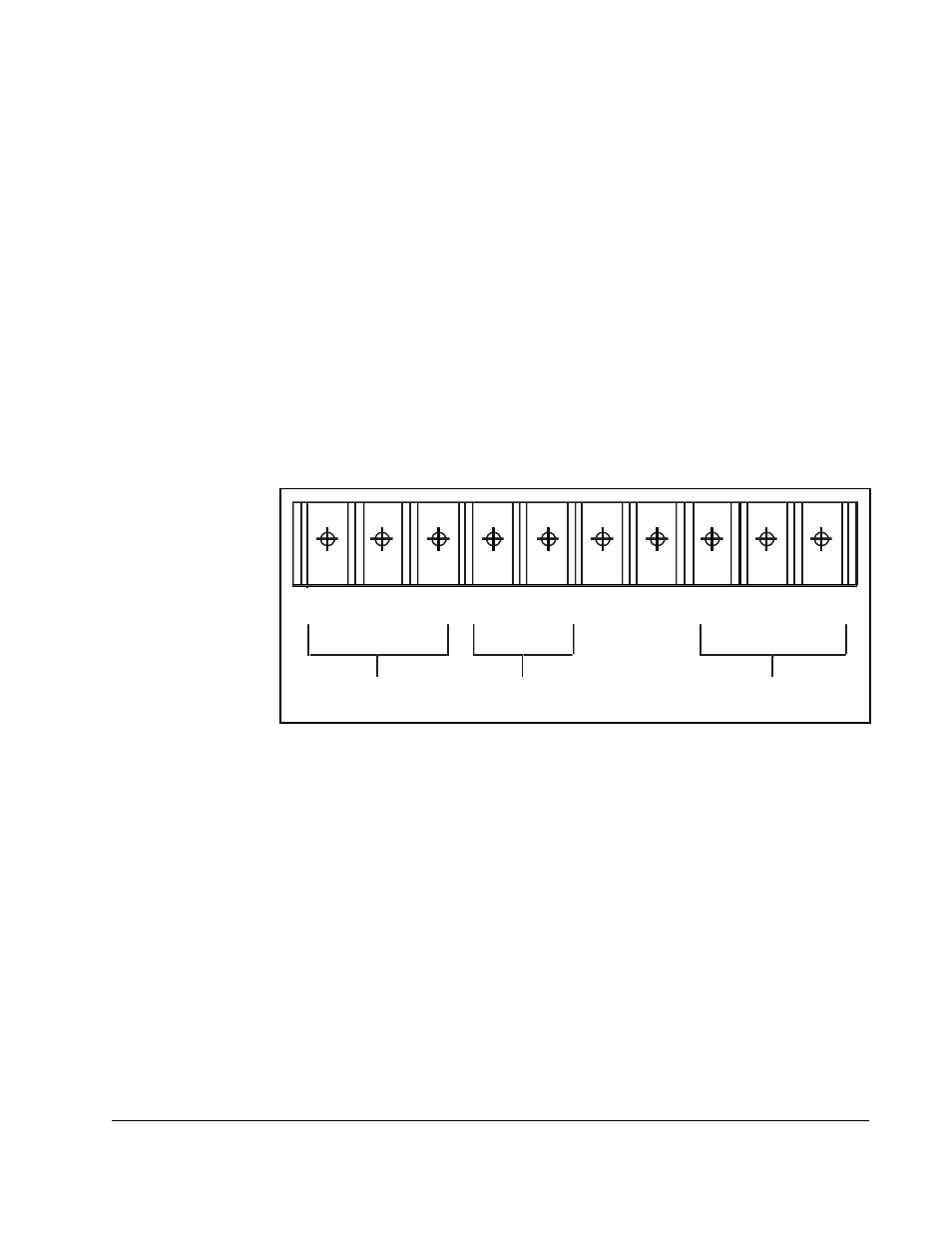
b. Use a voltmeter to measure the DC bus potential at the DC bus power
terminals shown in figure 2.6.
Step 3.
Remove the Keypad Bracket from the Drive
Step 3.1 Record connections to the Regulator board terminal strip if they must be
disconnected to remove the keypad bracket.
Step 3.2 Use a magnetic screwdriver to remove the M4 x 10 screws that fasten the
bottom of the keypad support bracket to the drive heat sink.
Step 3.3 Spread the retaining clips on the Regulator board ribbon cable (on the right
side) to disconnect it from the Base Board.
Step 3.4 Remove the keypad bracket. Place it with the keypad down on a flat
surface. If you cannot lay it flat, tie it up to prevent damage to wiring.
Figure 2.6 – DC Bus Voltage Terminals (1 to 20HP @ 230 V)
W/ T3
V/T2
U /T1
+
S/L2
1 0V
1 0 COM
Motor Leads
AC Power
Input Leads
DC Bus
Volts
R/L1
T/L3
–
+
–