Rockwell Automation GV3000/SE AC Drive AutoMax Network Communication Board, M/N 2AX3000 User Manual
Page 14
Installation
2-5
Step 2.
Verify That the DC Bus Capacitors are Discharged
Step 2.1 Use a voltmeter to verify that there is no voltage at the drive’s AC input
power terminals (R/L1, S/L2, T/L3).
Step 2.2 Ensure that the DC bus capacitors are discharged. To check
DC bus potential:
a. Stand on a non-conductive surface and wear insulated gloves.
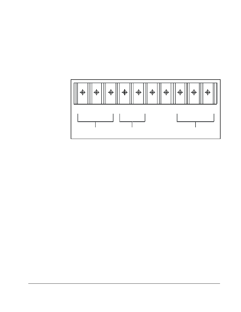
b. Use a voltmeter to measure the DC bus potential at the DC bus power
terminals as shown in figure 2.2.
Step 3.
Remove the Keypad Bracket from the Drive
Step 3.1 Record connections to the Regulator board terminal strip if they must be
disconnected to remove the keypad bracket.
Step 3.2 Use a magnetic screwdriver to remove the three M4 x 10 screws that fasten
the bottom of the keypad support bracket to the drive heat sink.
Important: The keypad support bracket is connected to the drive by wiring. Do not lift
the bracket completely out of the drive to prevent damage to wiring.
Step 3.3 Spread the retaining clips on the 26-conductor Regulator board ribbon
cable connector to disconnect it from the Current Feedback board. The
Current Feedback board is located on the right below the keypad.
Step 3.4 Move the keypad support bracket aside.
Step 3.5 Pinch the retaining clip that is through the center of the Current Feedback
board and carefully pull out the Current Feedback board.
Step 3.6 Unplug the internal fan assembly power connector (CONN7) from the drive.
Figure 2.2 – DC Bus Voltage Terminals (1 to 5HP @ 460 V)
W/ T3
V/T2
U /T1
+
S/L2
1 0V
1 0 COM
Motor Leads
AC Power
Input Leads
DC Bus
Volts
R/L1
T/L3
–
+
–