Setting the automax network option board jumpers, 1 setting automax network option board jumpers – Rockwell Automation GV3000/SE AC Drive AutoMax Network Communication Board, M/N 2AX3000 User Manual
Page 12
Installation
2-3
2.1
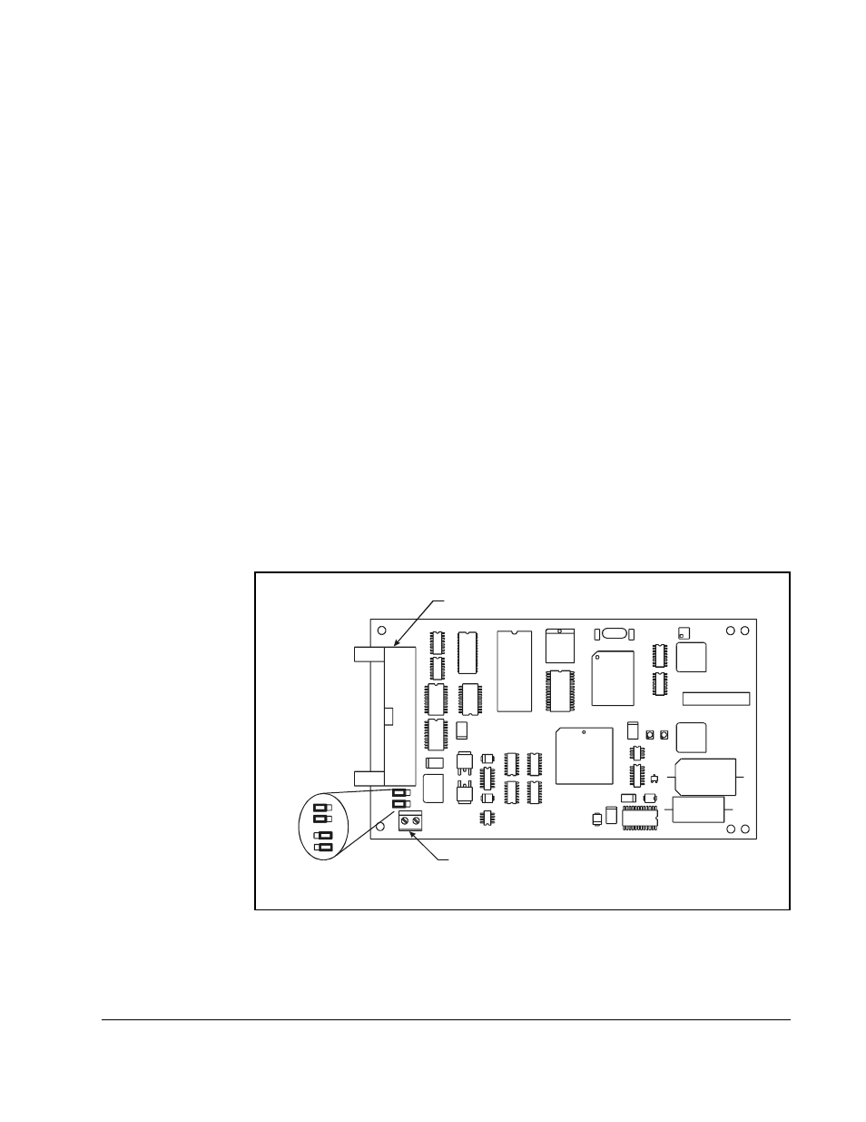
Setting AutoMax Network Option Board Jumpers
The AutoMax Network option board is shipped with jumpers J4 and J5 connecting
pins 1 and 2 (see figure 2.1).
You must change the position of jumpers J4 and J5 to connect pins 2 and 3 before
installing the AutoMax Network option board if your drive is one of these model
numbers:
To check the jumpers, remove the AutoMax Network option board from its anti-static
wrapper. See figure 2.1 for jumper locations.
After changing or checking the jumpers, place the AutoMax Network option board
back in its anti-static wrapper.
50R41xx
38ER40xx
126ET40xx
50T41xx
38ET40xx
150ER40xx
75R41xx
55ER40xx
150ET40xx
75T41xx
55ET40xx
240ER40xx
125R41xx
85ER40xx
240ET40xx
31ER40xx
85ET40xx
300ER40xx
31ET40xx
126ER40xx
300ET40xx
Figure 2.1 – Jumper Locations on AutoMax Network Option Board
IC
2
3
IC4
IC
2
4
IC19
IC25
IC7
J2
IC26
C4
C5
N2
Z1
XFMR1
N1
IC
2
2
IC
1
7
IC
1
3
IC
1
2
IC
1
6
Z2
IC2
C69
IC
1
1
IC
2
1
LED1 LED2
D1
C1
IC9
+
J3
IC10
C6
6
C6
7
CRY1
IC3
IC
2
0
IC
1
8
IC6
IC5
Z3
C68
C3
D2
IC8
L1
IC
1
J4
J5
J1
1 2 3
J4
J5
1 2 3
J4
J5
Jumpers
J4 and J5
Terminal Connections to
Passive Tap
Ribbon Connector to
Regulator Board
- 20P PowerFlex DC Drive - Frame D Bimetal Thermostat (10 pages)
- 1336S_F_T_E_R F Frame Snubber Resistor Repl. (6 pages)
- 22-COMM PowerFlex 4-Class DSI (Drive Serial Interface) Network Communication Adapter (4 pages)
- 8-545 Plug In Solid State Relay (2 pages)
- 20-HIM-B1 PowerFlex 7-Class HIM Bezel (DPI) (4 pages)
- 100 Contactors with DC Coil (1 page)
- 100 Contactors with DC Coil (2 pages)
- 20P PowerFlex DC Drive - Frame D Switching Power Supply Circuit Board (6 pages)
- 140G-MTFx_MTHx_MTIx_MTKx Trip Unit Installation-140G-M (6 pages)
- 45BRD Analog Laser Sensor (4 pages)
- 20D Multi-Device Interface Option Board for PowerFlex 700S Drives (20 pages)
- 56RF RFID 18 mm Cylindrical Transceiver (2 pages)
- 42KC Miniature Rectangular: 5V DC Version (2 pages)
- 20P PowerFlex DC Drive - Frame A Switching Power Supply Circuit Board (16 pages)
- 21P-MISC-A-TP-2 Transition Tube Kit #C19-6/7 For PowerFlex 755 w/OEM Liquid Cooling Fr 6/7 Drive (2 pages)
- 42BT Background Suppression Sensor (3 pages)
- 42CB High Speed 18mm Cylindrical (4 pages)
- 140EX-JE2_JE3 Molded Case Circuit Breaker (4 pages)
- 140G-K-EAM1A Early Make Aux Contact for Rotary Handle Oper Mech-140G-K (1 page)
- 140G-K-EAM1A Early Make Aux Contact for Rotary Handle Oper Mech-140G-K (3 pages)
- 20-HIM-A6 PowerFlex (Human Interface Module) (74 pages)
- 42CF General Purpose 12mm Cylindrical (4 pages)
- 20D PowerFlex 700S Phase II Drive Frames 1...6 (80 pages)
- 140EX-HE1_HE2 Molded Case Circuit Breaker (6 pages)
- 140EX-HE1_HE2 Molded Case Circuit Breaker (4 pages)
- 20B PowerFlex 700 Custom Firmware - Pump Off (12 pages)
- 20-WIM-N4S DPI Wireless Interface Module (92 pages)
- 140U H-Frame Circuit Breaker Fixed and Adjustable Thermal Trip (7 pages)
- 140U H-Frame Circuit Breaker Fixed and Adjustable Thermal Trip (2 pages)
- 60-2619, 42JS Swivel/Tilt Mounting Bracket (1 page)
- 22A PowerFlex 4/40/400 Flange Mount (4 pages)
- 45MLA Controller Installation Instructions (16 pages)
- 20P PowerFlex DC Drive - Cooling Fan for Frame A Drives Above 73A at 230V 460V AC (6 pages)
- 42JS Series 7000 to 42JS VisiSight Replacement Kit (2 pages)
- 22A PowerFlex 4-Class HIM Bezel (DSI) (4 pages)
- 42CS Stainless Steel Photoelectric Sensors (4 pages)
- 20L-LL PowerFlex 700L Liquid-to-Liquid Heat Exchanger (40 pages)
- 20P PowerFlex DC Drive - Frame B SCR Modules (20 pages)
- 22B PowerFlex 40 Quick Start FRN 5.xx - 6.xx (161 pages)
- 22B PowerFlex 40 Quick Start FRN 5.xx - 6.xx (22 pages)
- 22F PowerFlex 4M Input RFI Filters (2 pages)
- 45LFM Capacitive Label Sensor (4 pages)
- 140G-Rx Installation Instruction-140G-R (2 pages)
- 140G-Rx Installation Instruction-140G-R (29 pages)
- 22C PowerFlex 400 AC Drive Quick Start - FRN 1-4.xx (28 pages)