Rockwell Automation GV3000/SE AC Drive AutoMax Network Communication Board, M/N 2AX3000 User Manual
Page 19
2-10
AutoMax Network Communication Option Board for the GV3000/SE AC Drive
Step 4.
Install the AutoMax Network Option Board in the Keypad Bracket
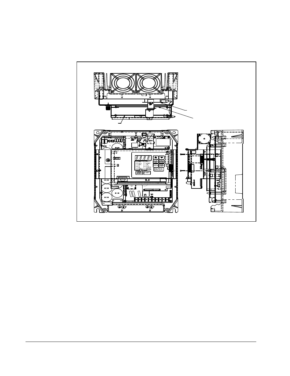
Refer to figure 2.5 for component locations.
Step 4.1 Remove the AutoMax Network option board from its anti-static wrapper.
Step 4.2 Align the key on the connector of the AutoMax Network option board ribbon
cable with the key on the Regulator board connector. Press the ribbon
cable connector in until it locks into position.
Step 4.3 Route the 26-conductor ribbon cable for the Current Feedback board out of
the side of the keypad bracket.
Step 4.4 Align the AutoMax Network option board on the four mounting tabs on the
keypad bracket. Make sure that the ribbon cable is not pinched between the
keypad bracket and the AutoMax Network option board.
Step 4.5 Fasten the right side of the AutoMax Network option board to the keypad
bracket. Use the two metal M3 screws and lock washers for grounding.
Important: You must use the lock washers to properly ground the option board.
Improper grounding of the option board can result in erratic operation of
the drive.
Figure 2.5 – 7.5 to 10HP @ 460V GV3000/SE Drive
Side View
Front View
Top View
Network Option Board
Regulator Board
Current Feedback Board