Rockwell Automation GV3000/SE AC Drive AutoMax Network Communication Board, M/N 2AX3000 User Manual
Page 31
2-22
AutoMax Network Communication Option Board for the GV3000/SE AC Drive
Important: Read and understand the warning labels on the outside of the drive
before proceeding.
Step 1.
Shut Down the Drive
Step 1.1 Disconnect, lock out, and tag all incoming power to the drive.
Step 1.2 Wait five minutes for the DC bus capacitors to discharge.
Step 1.3 Remove the cover by loosening the four cover screws.
Important: Read and understand the warning labels on the inside of the drive before
proceeding.
Step 2.
Verify That the DC Bus Capacitors are Discharged
Step 2.1 Use a voltmeter to verify that there is no voltage at the drive’s AC input
power terminals (R/L1, S/L2, T/L3).
Step 2.2 Ensure that the DC bus capacitors are discharged. To check
DC bus potential:
a. Stand on a non-conductive surface and wear insulated gloves.
b. Use a voltmeter to measure the DC bus potential at the DC bus power
terminals as shown in figures 2.11 (15 to 25 HP) and 2.12 (25 to 60 HP).
Step 3.
Remove the Keypad Bracket from the Drive
Step 3.1 Record connections to the Regulator board terminal strip if they must be
disconnected to remove the keypad bracket.
Step 3.2 Loosen the thumb screw on the left side of the keypad bracket. Hold the
bracket on the left and lift the bracket up and to the left to separate it from
the keypad support bracket.
Important: The bracket is connected to the drive by wiring. Do not attempt to lift the
bracket out completely as this can damage or pull out wiring. Tie up or
support the bracket to prevent damage to the wiring.
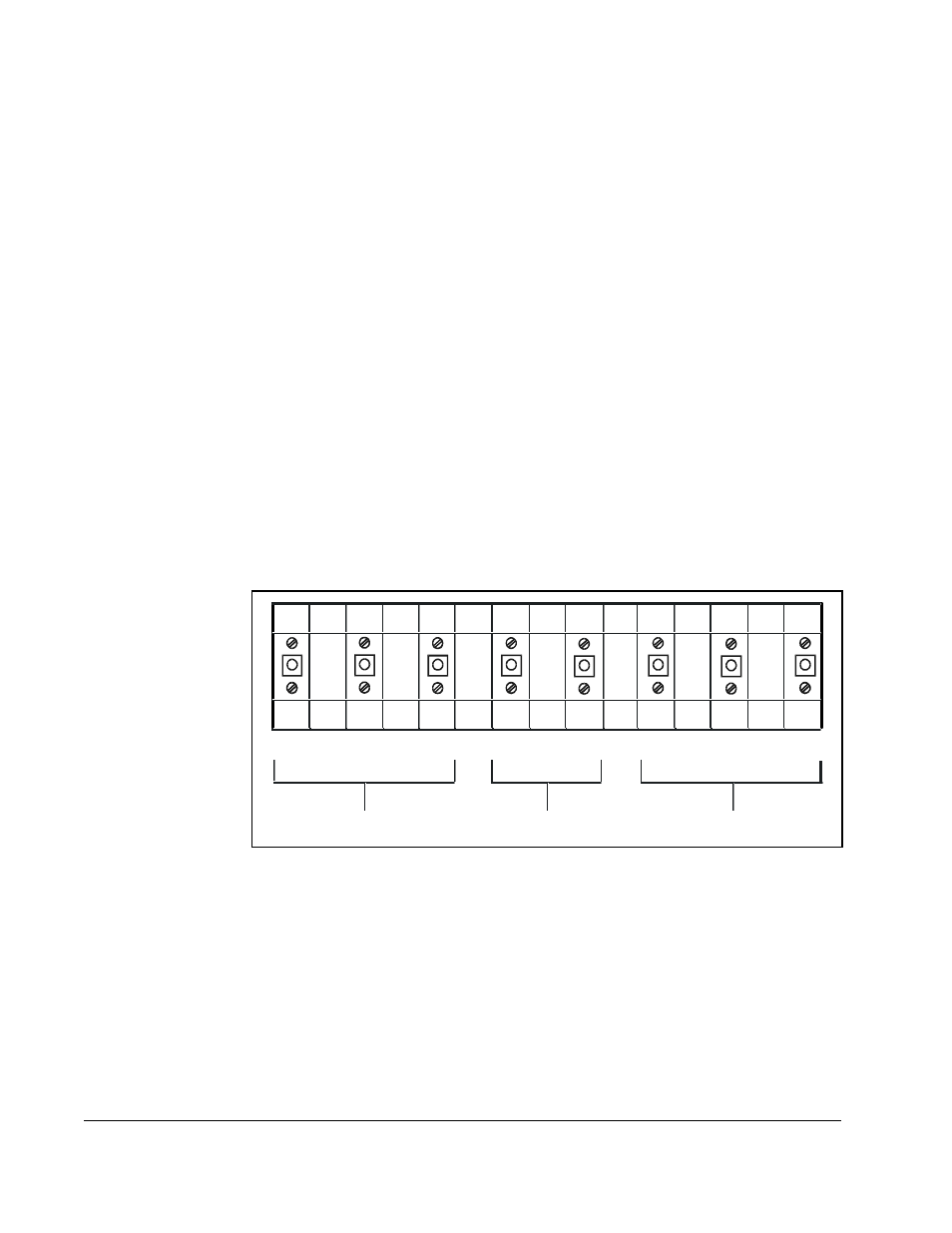
Figure 2.11 – DC Bus Voltage Terminals (15 to 25 HP @ 460 V)
Motor Leads
AC Power
Input Leads
DC Bus
Volts
+
V/T2
U/ T1
T/L3
S/L2
R/L1
W/ T3
–