Rockwell Automation GV3000/SE AC Drive AutoMax Network Communication Board, M/N 2AX3000 User Manual
Page 32
Installation
2-23
Step 3.3 Disconnect the 26-conductor Regulator board ribbon cable from the Power
Supply board (located on the right side below the keypad). You can see the
connector through the slot on the keypad support bracket. Use a small
screwdriver inserted through the slot to spread the retaining clips on the
connector to release it.
Step 4.
Install the AutoMax Network Option Board in the Keypad Bracket
Refer to figure 2.13 for component locations.
Step 4.1 Remove the AutoMax Network option board from its anti-static wrapper.
Step 4.2 Align the key on the connector of the AutoMax Network option board ribbon
cable with the key on the Regulator board connector. Press the ribbon
cable connector in until it locks into position.
Step 4.3 Align the AutoMax Network option board on the four mounting tabs on the
keypad bracket. Make sure that the ribbon cable is not pinched between the
keypad bracket and the AutoMax Network option board.
Step 4.4 Fasten the right side of the AutoMax Network option board to the keypad
bracket. Use the two metal M3 screws and lock washers for grounding.
Important: You must use the lock washers to properly ground the option board.
Improper grounding of the option board can result in erratic operation of
the drive.
Step 4.5 Fasten the left side of the AutoMax Network option board to the keypad
bracket using the two plastic rivets.
Step 4.6 Realign the 26-conductor ribbon cable connector with the Power Supply
board connector inside the slot in the keypad support bracket. Carefully
press the ribbon cable connector in until the retaining clips lock it into place.
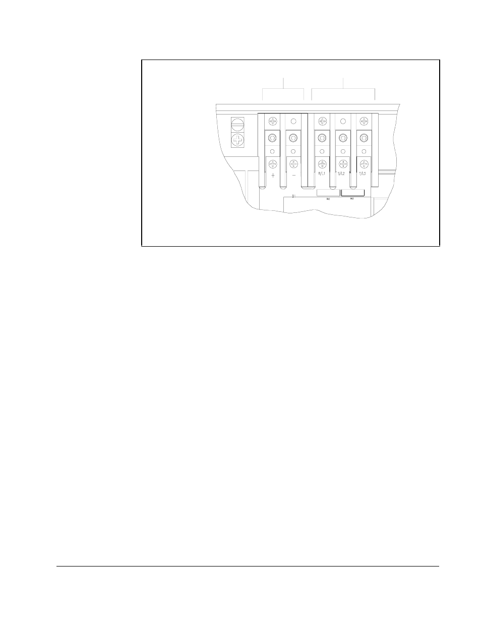
Figure 2.12 – DC Bus Voltage Terminals (25 to 60 HP @ 460 V)
Input Wiring
DC Bus Volts