Rockwell Automation GV3000/SE AC Drive AutoMax Network Communication Board, M/N 2AX3000 User Manual
Page 27
2-18
AutoMax Network Communication Option Board for the GV3000/SE AC Drive
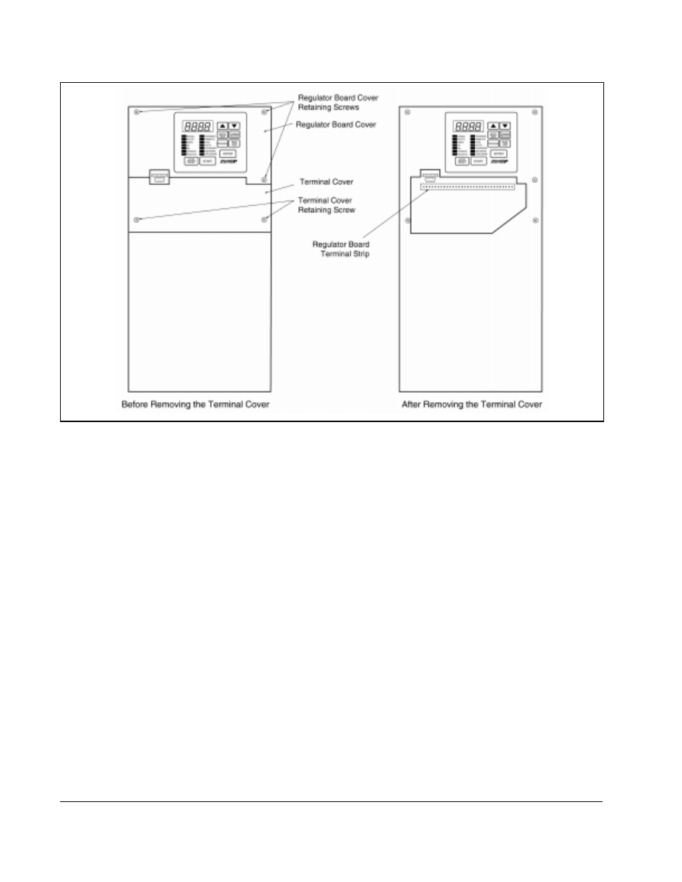
Step 3.2 Remove the terminal cover, which is below the keypad and fastened with
two M4 screws. See figure 2.9.
Step 3.3 Record connections to the Regulator board terminal strip if they must be
disconnected to remove the keypad bracket.
Step 3.4 Pull the keypad assembly partly out of the drive. Spread the retaining clips
on the Regulator board ribbon cable (on the right side) to disconnect it from
the Base Board. See figure 2.10.
Step 3.5 Remove the keypad bracket. Place it with the keypad down on a flat
surface. If you cannot lay it flat, tie it up to prevent damage to wiring.
Step 4.
Install the AutoMax Network Option Board in the Keypad Bracket
Refer to figures 2.9 and 2.10.
Step 4.1 Remove the AutoMax Network option board from its anti-static wrapper.
Step 4.2 Align the key on the connector of the AutoMax Network option board ribbon
cable with the key on the Regulator board connector. Press the ribbon
cable connector in until it locks into position.
Step 4.3 Route the other ribbon cable out of the side of the keypad bracket.
Step 4.4 Align the AutoMax Network option board on the four mounting tabs on the
keypad bracket. Make sure that the ribbon cable is not pinched between the
keypad bracket and the AutoMax Network option board.
Figure 2.9 – Location of Terminal Cover and Regulator Board Cover in 30 to 100 HP @ 230 VAC and 75 to 200 HP @ 460 VAC Drives