T069, T072, Terminal block group (continued) – Rockwell Automation 25B PowerFlex 520-Series Adjustable Frequency AC Drive User Manual User Manual
Page 85
Rockwell Automation Publication 520-UM001G-EN-E - September 2014
85
Programming and Parameters
Chapter 3
Terminal Block Group (continued)
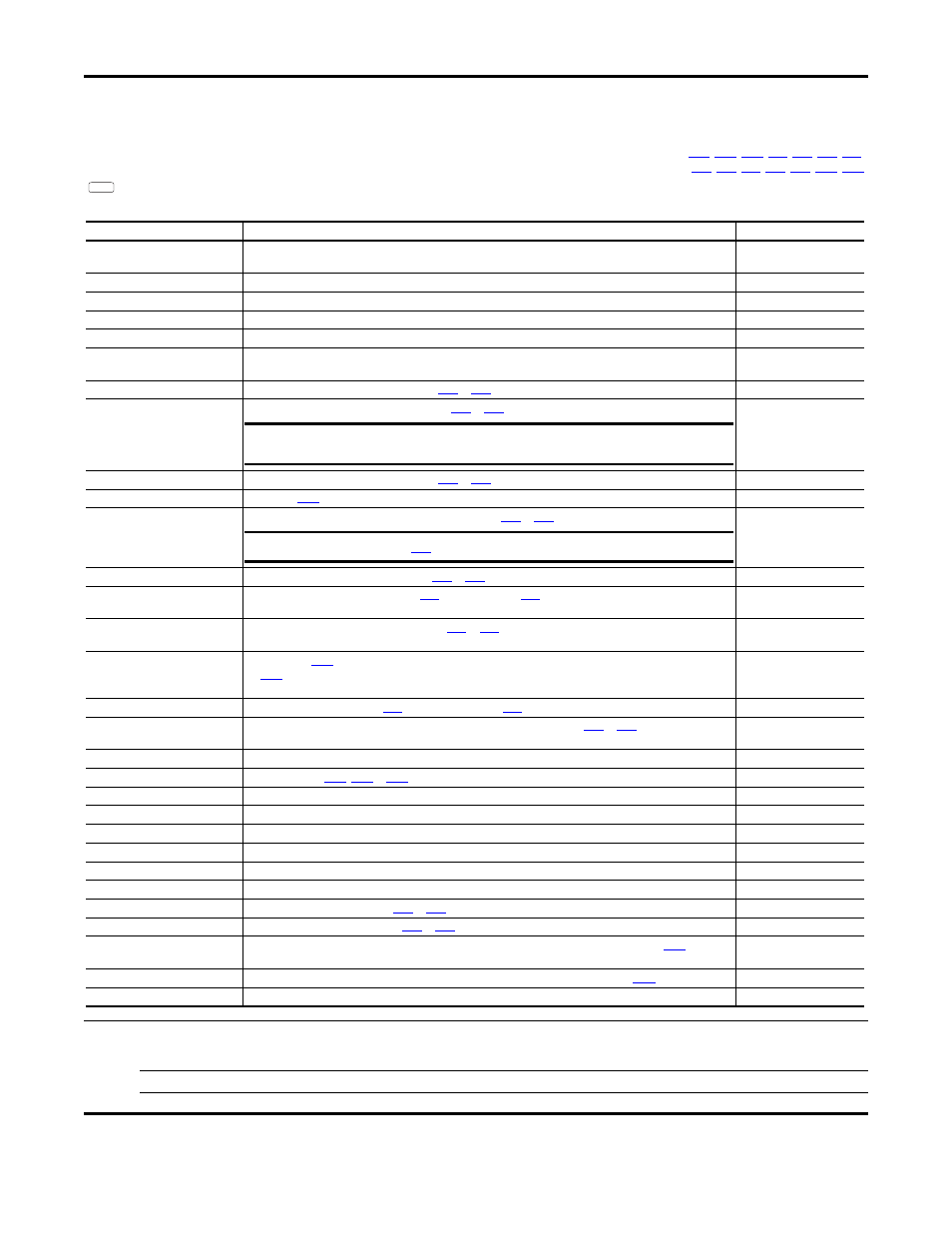
t069 [Opto Out1 Sel]
Related Parameter(s):
,
t072 [Opto Out2 Sel]
,
PowerFlex 525 only.
Determines the operation of the programmable digital outputs.
Values
Default:
Opto Out1 Sel:
Opto Out2 Sel:
2
1
Min/Max:
0/29
Display:
1
PF 525
Options
Setting Output Changes State When...
Hysteresis
0 “Ready/Fault”
Opto outputs are active when power is applied. Indicates that the drive is ready for operation. Opto outputs are
inactive when power is removed or a fault occurs.
None
1 “At Frequency”
Drive reaches commanded frequency.
0.5 Hz above; 1.0 Hz below
2 “MotorRunning”
Motor is receiving power from the drive.
None
3 “Reverse”
Drive is commanded to run in reverse direction.
None
4 “Motor Overld”
Motor overload condition exists.
100 ms time delay on or off
5 “Ramp Reg”
Ramp regulator is modifying the programmed accel/decel times to avoid an overcurrent or overvoltage fault from
occurring.
100 ms time delay on or off
6 “Above Freq”
Drive exceeds the frequency (Hz) value set in
[Opto Outx Level].
100 ms time delay on or off
7 “Above Cur”
Drive exceeds the current (% Amps) value set in
100 ms time delay on or off
8 “Above DCVolt”
Drive exceeds the DC bus voltage value set in
[Opto Outx Level].
100 ms time delay on or off
9 “Retries Exst”
Value set in
[Auto Rstrt Tries] is exceeded.
None
10 “Above Anlg V”
Analog input voltage (0-10V input) exceeds the value set in
[Opto Outx Level].
100 ms time delay on or off
11 “Above PF Ang”
Power Factor angle exceeds the value set in
[Opto Outx Level].
100 ms time delay on or off
12 “Anlg In Loss”
Analog input loss has occurred. Program
[Anlg In V Loss] or
[Anlg In mA Loss] for desired action when
input loss occurs.
On, 2 mA / ±1V
Off, 3 mA / ±1.5V
13 “ParamControl”
Output is directly controlled by the state of the
or
[Opto Outx Level]. A value of 0 causes the output to
turn off. A value of 1 or greater in this parameter causes the output to turn on.
None
14 “NonRec Fault”
[Auto Rstrt Tries] is exceeded or
•
[Auto Rstrt Tries] is not enabled or
• A non-resettable fault has occurred.
None
15 “EM Brk Cntrl”
EM Brake is energized. Program
[EM Brk On Delay] and
[EM Brk Off Delay] for desired action.
None
16 “Thermal OL”
Relay energizes when thermal Motor overload counter is above the value set in
[Relay Outx Level]. It
also energizes if the drive is within 5
°C of the drive overheat trip point.
None
17 “Amb OverTemp”
Relay energizes when control module over temperature occurs.
None
18 “Local Active”
Active when drive
[Start Source x] is in local keypad control.
None
19 “Comm Loss”
Active when communication is lost from any comm source with reference or control.
None
20 “Logic In 1”
An input is programmed as “Logic Input 1” and is active.
None
21 “Logic In 2”
An input is programmed as “Logic Input 2” and is active.
None
22 “Logic 1 & 2”
Both Logic inputs are programmed and active.
None
23 “Logic 1 or 2”
One or both Logic inputs are programmed and one or both is active.
None
24 “StpLogic Out”
Drive enters StepLogic step with Command Word set to enable Logic output.
None
25 “Timer Out”
Timer has reached the value set in
[Opto Outx Level] or not timing.
None
26 “Counter Out”
Counter has reached the value set in
[Opto Outx Level] or not counting.
None
27 “At Position”
Drive is in Positioning mode and has reached the commanded position. Tolerance is adjusted with
[Encoder
Pos Tol].
–
28 “At Home”
Drive is in Positioning mode and has reached the home position. Tolerance is adjusted with
29 “Safe-Off”
Both safe-off inputs are active.
–
IMPORTANT
Value for t070 or t073 [Opto Outx Level] must be entered in percent of drive rated output
current.
IMPORTANT
Do not use if
[10V Bipolar Enbl] is set to 1 “Bi-Polar In”.