Rockwell Automation 25B PowerFlex 520-Series Adjustable Frequency AC Drive User Manual User Manual
Page 24
24
Rockwell Automation Publication 520-UM001G-EN-E - September 2014
Chapter 1
Installation/Wiring
Fu
ses and Circ
uit Break
ers f
or P
ow
erFle
x 520-Series Driv
es
(c
ontinu
ed
)
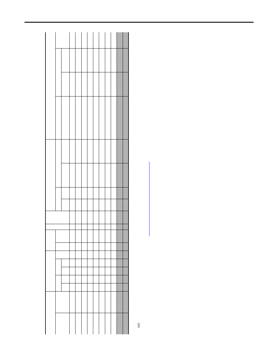
200...240V 3-Pha
se Input Pr
ot
ec
tion D
evic
es – F
rames A...E
(1)
Norm
al
D
ut
y (
N
D) a
nd Heav
y D
ut
y (
H
D)
ratings
ar
e a
vai
la
ble
for this
driv
e.
(2)
W
hen the
driv
e is c
on
tr
olling mot
ors
w
ith lo
w
er amp r
atings
, r
efe
r t
o the driv
e n
amepla
te for driv
e input c
urr
en
t r
ating
.
(3)
The
AI
C r
ati
ngs of
the B
ull
eti
n
140M Motor P
ro
te
ctor Ci
rc
uit B
rea
ke
rs m
ay v
ar
y. S
ee
.
(4)
Bulletin 1
40M with ad
justable curr
en
t r
ange should hav
e the cu
rr
en
t trip set t
o
the minimum r
ange tha
t the device will not t
rip
.
(5)
M
anua
l S
el
f-P
ro
te
ct
ed
(T
ype E
) C
om
bi
na
tio
n Mot
or C
ontr
ol
ler
, UL li
st
ed
for 480Y
/2
77 a
nd 600
Y/
347
A
C
in
put
. Not UL l
is
ted for
us
e on 48
0V or 600
V D
elta
/D
elta
, corner
gr
ound
, or hig
h-r
esistance gr
ound
syst
ems
.
(6)
W
hen using a Manual S
elf-P
rot
ec
ted
(T
ype E
) C
ombina
tion M
ot
or C
on
tr
oller with this driv
e po
w
er r
ating
, the dr
iv
e must be ins
ta
lled i
n a v
enti
la
te
d or non-v
enti
la
te
d encl
osur
e wi
th the m
ini
mum
v
ol
ume
spe
ci
fie
d in thi
s colum
n. Ap
pl
ic
at
io
n sp
eci
fic therm
al
co
ns
ide
ra
tio
ns m
ay r
equir
e a l
ar
ger enc
los
ur
e.
Ca
ta
log
N
o.
(1)
O
u
tpu
t Rati
ngs
In
pu
t
Ra
ti
ngs
Frame S
ize
Contac
tor
Cata
log
No.
IEC
A
p
plic
at
io
ns (No
n
-UL)
UL Applic
at
ions
PF
523
PF
525
ND
HD
Amps
kVA
Max
Amps
(2)
Fu
ses
(R
at
ing)
Ci
rc
uit
Brea
ke
rs
Fu
se
s (M
ax
. Ra
ti
ng)
Circ
u
it
Break
ers
Mi
n.
Enclosure
Vo
l. (i
n.
3
)
HP
kW
HP
kW
Min.
Max.
140U/140
G
14
0M
Class /
Ca
tal
og N
o.
14
0U/140G
14
0M
(3)(
4)(5)
25
A-
B1
P6N1
04
–
0.25
0.2
0.25
0.2
1.6
0.9
1.9
A
100-C09
3
6
140U
-D6
D3-
B3
0
140M
-C
2E
-B2
5
CLASS RK
5, C
C, J
, or
T /
DL
S-R
-15
140U
-D6
D3-B30
14
0M-C2E-B
25
–
25
A-
B2
P5N1
04
25
B-B2P
5N1
04
0.5
0.4
0.5
0.4
2.5
1.2
2.7
A
100-C09
6
6
140U
-D6
D3-
B4
0
140M
-C
2E-B4
0
CLASS RK
5, C
C, J
, or
T /
DL
S-R
-6
140U
-D6
D3-B40
14
0M-C2E-B40
–
25
A-
B5
P0N1
04
25
B-B5P
0N1
04
1.0
0.75
1.0
0.75
5.0
2.7
5.8
A
100-C09
10
16
140U
-D
6D3-
B8
0
140M
-C
2E-B6
3
CLASS RK
5, C
C, J
, or
T /
DL
S-R
-15
140U
-D6
D3-
B80
14
0M-C2E-B63
–
25
A-
B8
P0N1
04
25
B-B8P
0N1
04
2.0
1.5
2.0
1.5
8.0
4.3
9.5
A
100-C12
16
20
140U
-D6
D3-C10
140M
-C
2E-C10
CLASS RK
5, C
C, J
, or
T /
DL
S-R
-20
140U
-D6
D3-C1
0
14
0M-C2E-
C10
–
25
A-
B0
11N
104
25
B-B01
1N1
04
3.0
2.2
3.0
2.2
11.0
6.3
13.8
A
100-C23
20
32
140U
-D6
D3-C15
140M
-C
2E-C16
CLASS RK
5, C
C, J
, or
T /
DL
S-R
-30
140U
-D6
D3-
C15
14
0M-C2E-
C16
–
25
A-
B0
17N
104
25
B-B01
7N1
04
5.0
4.0
5.0
4.0
17.5
9.6
21.1
B
100-C23
32
45
140U
-D6
D3-C25
140M
-F8E-C25
CLASS C
C, J
, or
T /
45
140U
-D6
D3-C25
14
0M-
F8E
-C25
–
25
A-
B0
24N
104
25
B-B02
4N1
04
7.5
5.5
7.5
5.5
24.0
12.2
26.6
C
100-C37
35
63
140G
-G
6C3
-C3
5
140M
-F8E-C32
CLASS C
C, J
, or
T /
60
–
14
0M-
F8E-C32
–
25
A-
B0
32N
104
25
B-B03
2N1
04
10.0
7.5
10.0
7.5
32.2
15.9
34.8
D
100-C43
45
70
140G-
G6C3
-C6
0
140M
-F8E-C45
CLASS RK
5, C
C, J
, or
T /
DL
S-R
-70
–
14
0M-
F8E-C45
–
25
A-
B0
48N
104
25
B-B04
8N1
04
15.0
11.0
10.0
7.5
48.3
20.1
44.0
E
100-C60
63
90
140G-
G6C3
-C7
0
140M
-F8E-C45
CLASS C
C, J,
or
T /
90
–
14
0M-
F8E-C45
14
16.0
(6
)
25
A-
B0
62N
104
25
B-B06
2N1
04
20.0
15.0
15.0
11.0
62.1
25.6
56.0
E
100-C72
70
12
5
140G-
G6C3
-C9
0
–
CLASS C
C, J,
or
T /
125
–
–
–