I/o wiring examples – Rockwell Automation 25B PowerFlex 520-Series Adjustable Frequency AC Drive User Manual User Manual
Page 42
42
Rockwell Automation Publication 520-UM001G-EN-E - September 2014
Chapter 1
Installation/Wiring
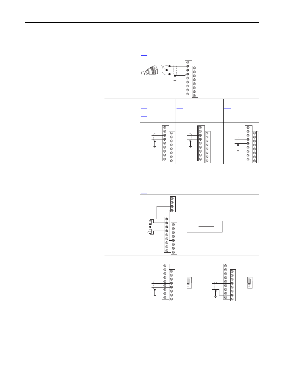
I/O Wiring Examples
I/O
Connection Example
Potentiometer
1...10k
Ω Pot.
Recommended
(2 W minimum)
[Speed Reference1] = 5 “0-10V Input”
Analog Input
0-10V, 100k
Ω impedance
4-20 mA, 250
Ω
impedance
Bipolar
[Speed Reference1]
= 5 “0-10V Input” and
[10V Bipolar Enbl]
= 1 “Bi-Polar In”
Unipolar (Voltage)
[Speed Reference1]
= 5 “0-10V Input”
Unipolar (Current)
[Speed Reference1]
= 6 “4-20mA Input”
Analog Input, PTC
For Drive Fault
Wire the PTC and External Resistor (typically matched to the PTC Hot Resistance) to I/O
Terminals 12, 13, 14.
Wire R2/R3 Relay Output (SRC) to I/O Terminals 5 & 11.
[DigIn TermBlk 05] = 12 “Aux Fault”
[Relay Out 2 Sel] = 10 “Above Anlg V”
[Relay Out 2 Level] = % Voltage Trip
Pulse Train Input
PowerFlex 523
t065 [DigIn TermBlk 05]
= 52
PowerFlex 525
t067 [DigIn TermBlk 07]
= 52
Use P047, P049 and P051
[Speed Referencex] to
select pulse input.
Jumper for DigIn TermBlk
05 or 07 Sel must be
moved to Pulse In.
12
13
14
13
14
±10V
Common
13
14
+
Common
14
15
Common
+
11
12
13
14
R5
R6
05
%VTrip =
X 100
RPTC (hot)
RPTC (hot) + Re
Re
RPTC
Common
PowerFlex 523
PowerFlex 525
Pulse In
05
04
D
igIn
TermBlk 05 S
el Pulse In
Digital
Input
Common
Pulse In
07
04
D
igIn
TermBlk 07 S
el Pulse In
Digital
Input