B013, Basic display group (continued), Important – Rockwell Automation 25B PowerFlex 520-Series Adjustable Frequency AC Drive User Manual User Manual
Page 73
Rockwell Automation Publication 520-UM001G-EN-E - September 2014
73
Programming and Parameters
Chapter 3
Basic Display Group (continued)
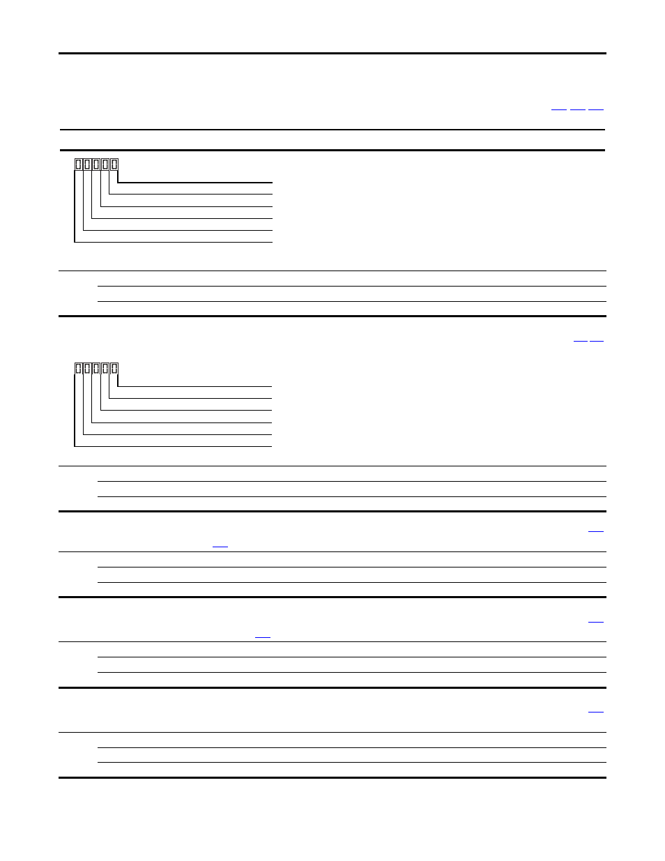
b013 [Contrl In Status]
State of the digital terminal blocks 1...3 and DB transistor.
Values
Default:
Read Only
Min/Max:
0000/1111
Display:
0000
IMPORTANT
Actual control commands may come from a source other than the control terminal block.
1 = Closed State, 0 = Open State
DigIn TBlk 1
Digit 1
DigIn TBlk 2
Digit 2
DigIn TBlk 3
Digit 3
DB Trans On
(1)
Digit 4
(1)
The DB Transistor “on” indication must have a 0.5 s hysteresis. It will turn on and stay
on for at least 0.5 s every time the DB transistor is turned on.
Not Used
b014 [Dig In Status]
Related Parameter(s):
State of the programmable digital inputs.
Values
Default:
Read Only
Min/Max:
0000/1111
Display:
0000
1 = Closed State, 0 = Open State
DigIn TBlk 5
Digit 1
DigIn TBlk 6
Digit 2
DigIn TBlk 7
(1)
Digit 3
(1)
Setting is specific to PowerFlex 525 drives only.
DigIn TBlk 8
(1)
Digit 4
Not Used
b015 [Output RPM]
Current output frequency in rpm. Scale is based on
[Motor NP Poles].
Values
Default:
Read Only
Min/Max:
0/24000 rpm
Display:
1 rpm
b016 [Output Speed]
Current output frequency in %. Scale is 0% at 0.00 Hz to 100% at
[Maximum Freq].
Values
Default:
Read Only
Min/Max:
0.0/100.0%
Display:
0.1%
b017 [Output Power]
Output power present at T1, T2 & T3 (U, V & W).
Values
Default:
Read Only
Min/Max:
0.00/(Drive Rated Power x 2)
Display:
0.01 kW