Functional proof test, Pfd and pfh data, Safety reaction time – Rockwell Automation 25B PowerFlex 520-Series Adjustable Frequency AC Drive User Manual User Manual
Page 226
226
Rockwell Automation Publication 520-UM001G-EN-E - September 2014
Appendix G
Safe-Torque-Off Function
•
access control to the system, including password handling.
•
analyzing all configuration settings and choosing the proper setting to
achieve the required safety rating.
Functional Proof Test
The PFD and PFH values provided in the table below are contingent upon the
Proof Test Interval (PTI). Before the end of the PTI specified in the table below,
a proof test of the STO safety function must be performed in order for the
specified PFD and PFH values to remain valid.
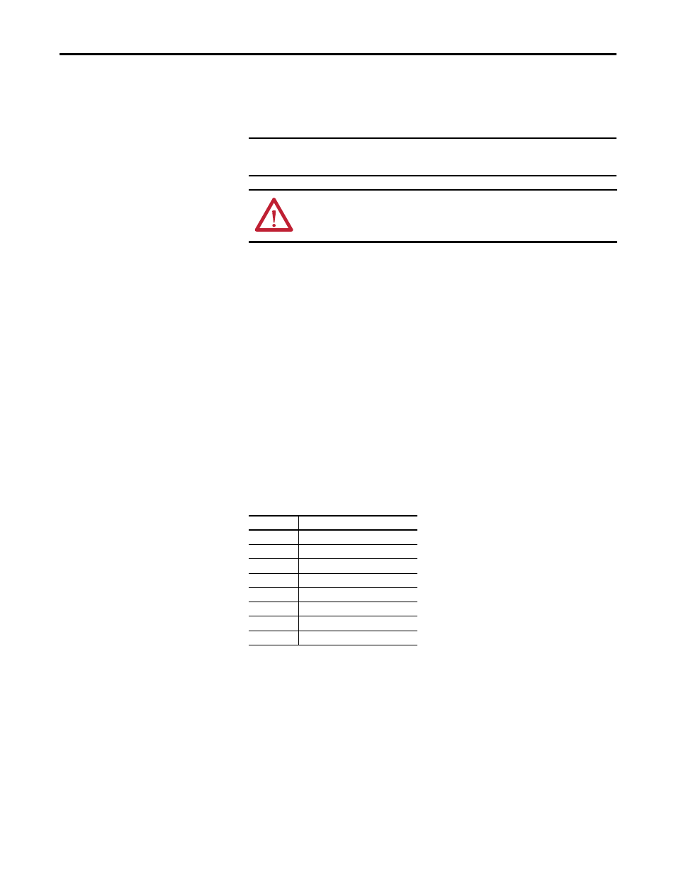
PFD and PFH Data
PFD and PFH
calculations are based on the equations from Part 6 of EN 61508.
This table provides data for a 20-year proof test interval and demonstrates the
worst-case effect of various configuration changes on the data.
PFD and PFH for 20-year Proof Test Interval
Safety Reaction Time
The safety reaction time is the amount of time from a safety-related event as
input to the system until the system is in the Safe State.
The safety reaction time from an input signal condition that triggers a safe stop,
to the initiation of safe-torque-off, is 100 ms (maximum).
IMPORTANT
When applying Functional Safety, restrict access to qualified, authorized
personnel who are trained and experienced.
ATTENTION: When designing your system, consider how personnel will exit
the machine if the door locks while they are in the machine. Additional
safeguarding devices may be required for your specific application.
Attribute
Value
PFD
6.62E-05 (MTTF = 3593 years)
PFH
D
8.13E-10
SFF
83%
DC
62.5%
CAT
3
HFT
1 (1oo2)
PTI
20 YEARS
Hardware Type Type A