Eqp logic editor – Det-Tronics S3 Graphics User Manual
Page 277
13-52
EQP LOGIC EDITOR
Version 6.0
EQP LOGIC EDITOR
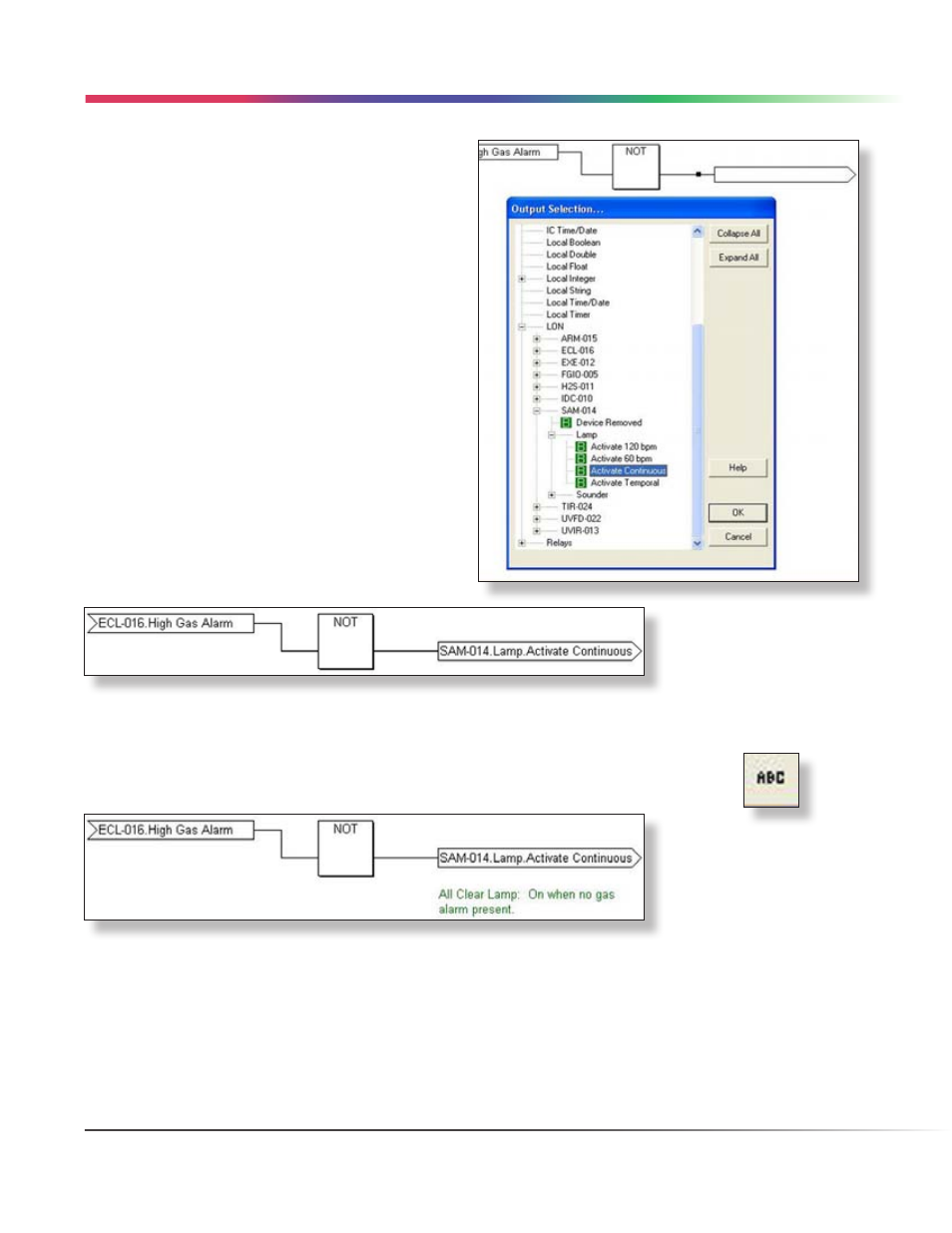
The final step in completing the example network is to
link the NOT gates output variable to an appropriate
point. Double clicking on the “Output Variable” opens
the “Output Selection...” dialog box.
This dialog box presents the database in the same
manner as described on the previous page for the
input selection process.
For this example, the LON data structure has been
expanded, a Signal Audible Module (SAM) with the
tagname “SAM-014” has been expanded and the
Binary data point “Activate Continuous” for the Lamp
output has been selected. Selecting the “OK” button
will close the “Output Selection...” dialog box and link
this output to the output variable as shown below.
The network is now complete, when the High Gas Alarm for ECL-016 goes “ON” the lamp controlled by SAM-014
goes “OFF”.
Using the “Comment Tool” a description can be added to explain the purpose of the output.
LOGIC CREATION • VARIABLE LINKING