Eqp logic editor – Det-Tronics S3 Graphics User Manual
Page 275
13-50
EQP LOGIC EDITOR
Version 6.0
EQP LOGIC EDITOR
Once this connection is established, the input variable can be repositioned anywhere left of its connection
point and the connection wire will change size and shape to keep the connection.
Using Wires
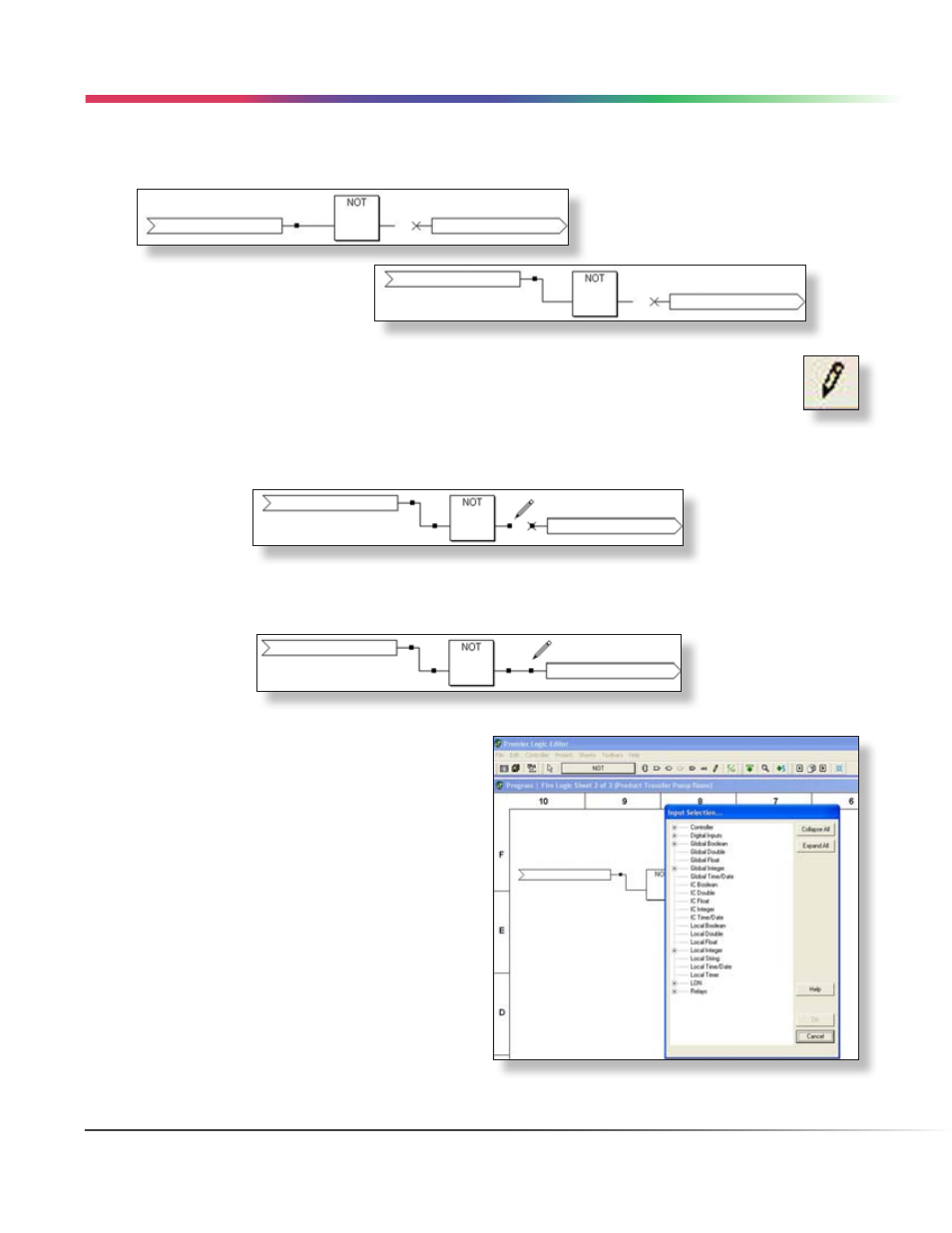
Click on the “Wire Tool” to activate it. The cursor changes to a miniature wire tool or pencil when it is
positioned anywhere within the drawing area of the sheet. This means that wires can be drawn from
one logic operator to another to connect them.
When active, the wire tool appears as in the example below. Using the wire tool, connect the output of the NOT
gate to the input of the Output Variable. This will complete the drawing of this three logic operator network.
Next, the Input Variable and Output Variable must be “linked” to an appropriate I/O point or memory location in
the controller.
Linking Variables
Input and output variables must be linked to compatible
field device or controller memory data. Using the three
logic operator “example network” created on the previous
page, double-clicking on the “Input Variable” will open
the “Input Selection...” dialog box which provides access
to the Eagle Quantum Premier’s database.
LOGIC CREATION • VARIABLE LINKING