Eqp logic editor – Det-Tronics S3 Graphics User Manual
Page 230
EQP LOGIC EDITOR
13-5
EQP LOGIC EDITOR
Version 6.0
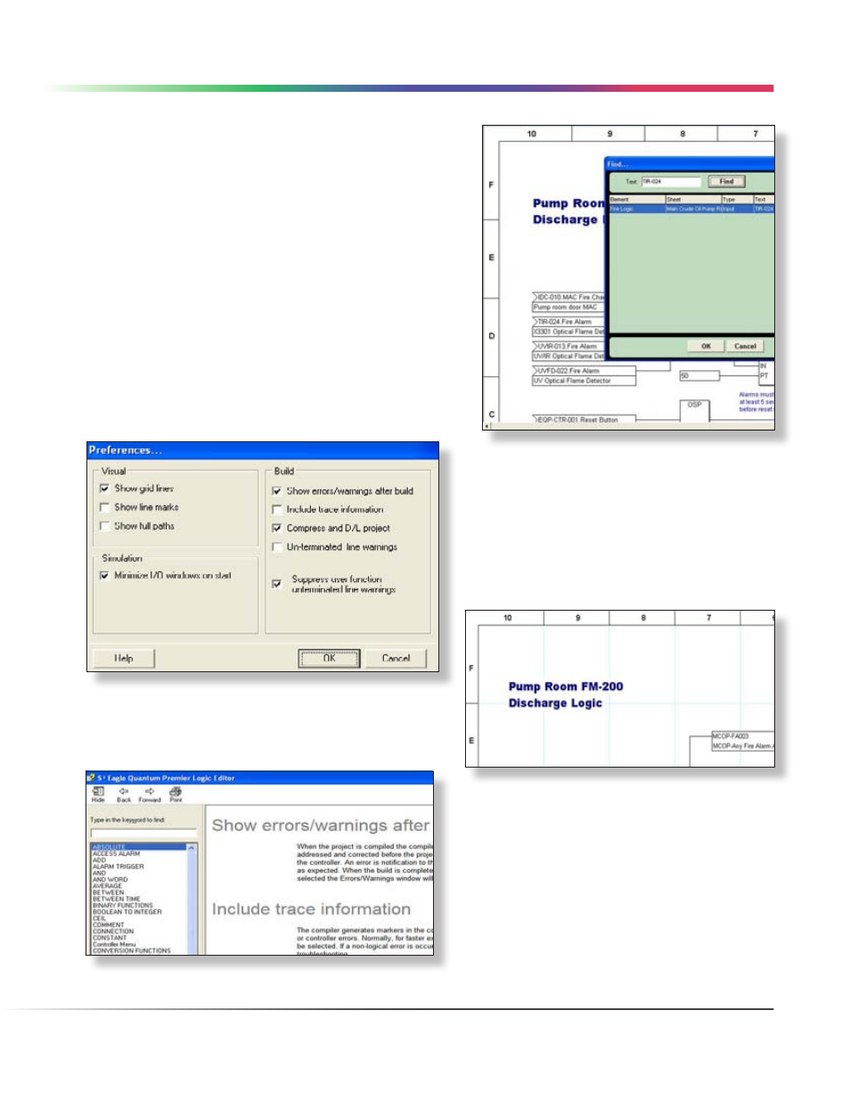
In this sample find, the listed Element is “Fire Logic” which
is a program, the Sheet Name in the logic program is “Main
Crude Oil Pump Room”, the Type is “Input” and finally the
located “Text” is “TIR-024”.
In the example to the right, the input block “TIR-024 Fire Alarm”
is on the left side of the logic page partially behind the “Find...”
dialog box.
Preferences
This selection opens the “Preferences...” dialog box which
contains a number of checkbox selections pertaining to the
visual display of the logic editor, compiling (Build) options and
a Simulator selection.
The example below shows the logic editors default
configuration. Each of these selectable options are described
in detail below.
Show grid lines
When selected this will display a faint cyan reference
lines on the drawing pages that correspond to the
horizontal and vertical references on the drawing
title block.
The grid lines are drawn “behind” the graphic logic
elements.
Use the “Help” function for additional information on
how each checkbox affects the look and feel of a
project.
LOGIC EDITOR • EDIT MENU