3 hydraulic pressure diagnosis, 1 pressure checks and adjustments, Hydraulic pressure diagnosis – JLG G12-55A AccuPlace Service Manual User Manual
Page 94: Pressure checks and adjustments
Hydraulic System
8.4
G10-55A & G12-55A AccuPlace
8.3
HYDRAULIC PRESSURE DIAGNOSIS
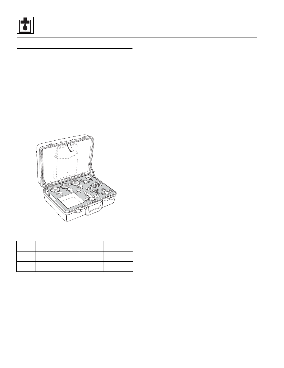
JLG Parts Department has a kit available to use for
hydraulic system maintenance and troubleshooting: the
JLG Pressure Test Kit. The kit is contained in a durable
polyethylene carrying case for demanding field service
conditions.
Pressure Test Kit
The hydraulic pressure test kit is used to pressure test the
various hydraulic components in the hydraulic system.
The kit includes:
• Gauges for testing high and low pressure circuits
• Fittings, couplers and hoses
Contact JLG Parts Department at 717-485-6472 for
ordering information.
8.3.1
Pressure Checks and Adjustments
When diagnosing trouble in the hydraulic system, use the
hydraulic testing information in Section 8.4.1, “Hydraulic
Pressures.”
In general, follow the steps below whenever conducting
pressure checks and performing adjustments:
1. Park the machine on a firm, level surface. Engage
the park brake, place the travel select lever in (N)
NEUTRAL, level the boom and turn the engine OFF.
2. The test ports are located on the hydraulic manifold
in the engine compartment. Install a pressure gauge
capable of measuring at least 10% more pressure
than that which the circuit being checked operates
under.
3. Start the engine. Operate machine functions several
times to allow hydraulic oil to reach operating
temperature. The hydraulic oil temperature should
be between 100-120° F (38-49° C). If a temperature
gauge or thermometer is unavailable, the hydraulic oil
reservoir should be warm to the touch.
4. Refer to Section 8.4.1, “Hydraulic Pressures,” for
testing procedures.
5. Fully depress the accelerator pedal if required. Place
and hold the joystick in the position needed to
operate the particular machine function being
checked. Continue holding the joystick in position
until pressure readings are taken.
6. Check the pressure gauge reading. It should read as
specified in the Pressure Range column of the
charts found in Section 8.4.1, “Hydraulic Pressures.”
If the reading is not as specified, turn the engine
OFF and check other components in the system.
Verify that all related hydraulic components and
electrical switches, sensors, solenoids, etc. are
operating correctly.
7. Adjust the relief valve by turning the adjustment
screw. Turning clockwise will increase the pressure;
turning the screw counterclockwise will decrease the
pressure.
8. Start the engine and check the pressure again. Turn
the engine OFF. If there is pressure reading in the
gauge, bleed it off then disconnect or remove the
pressure gauge from the machine.
Part
Number
Description
Approximate
Weight
Price and
Availability
70000652
Hydraulic Pressure
Test Kit
10 lbs.
Consult Factory
70000101
Digital Hydraulic
Pressure Test Kit
7 lbs.
Consult Factory
MZ1460