8 diagnostic trouble code (dtc) table, Section, 8, “diagnostic trouble code (dtc) table – JLG G12-55A AccuPlace Service Manual User Manual
Page 177: Diagnostic trouble code (dtc) table
9.59
G10-55A & G12-55A AccuPlace
Electrical System
9.15.8
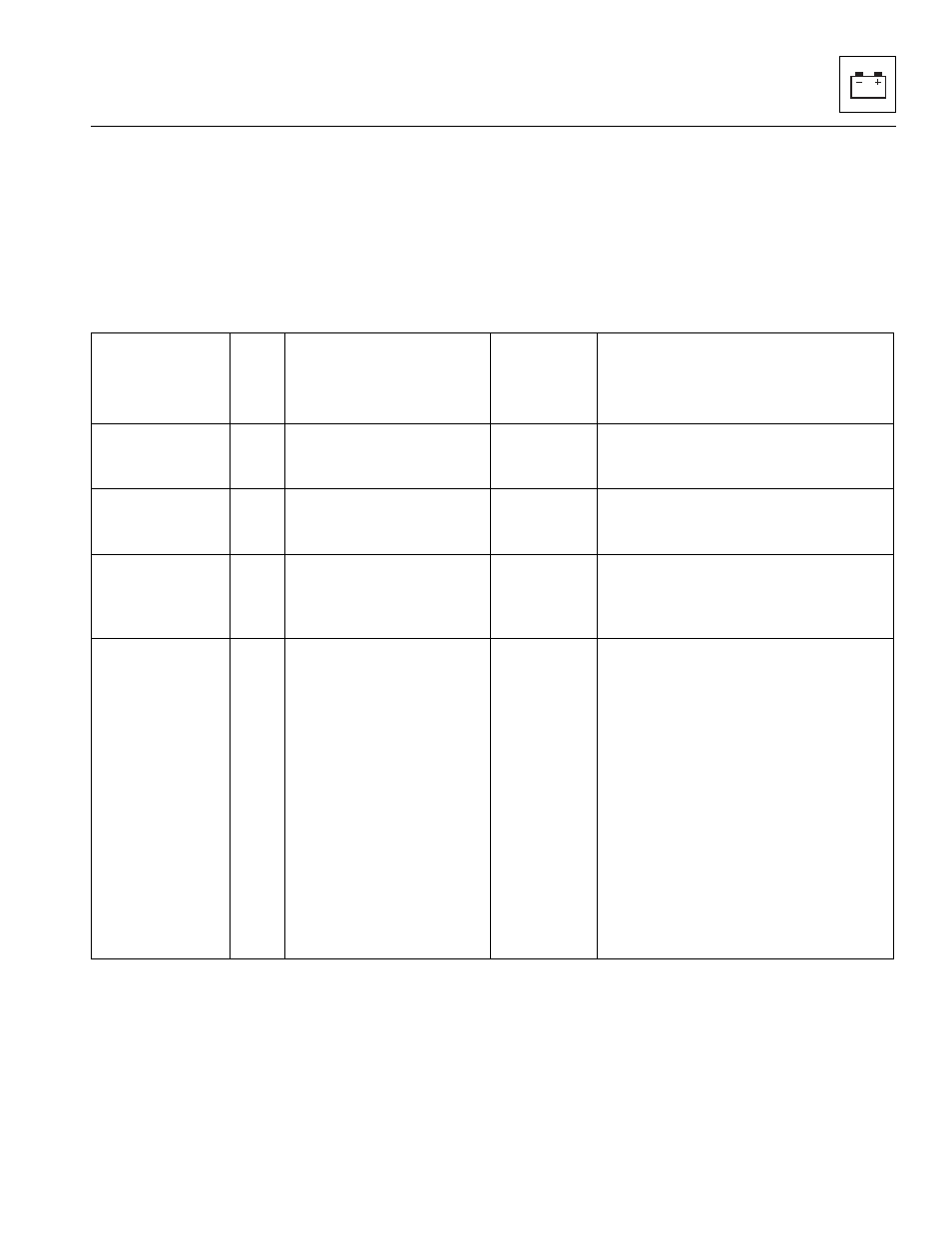
Diagnostic Trouble Code (DTC) Table
Note: The column labeled “Fault Requires AccuPlace
Reset” indicates whether the AccuPlace Mode Fault
Reset button is required to be pushed if a fault occurs
while operating in AccuPlace mode (Y = Yes, N = No). In
addition to pressing the Reset button if in AccuPlace
mode even if not explicitly stated, the conditions under
the “Action” description are required. Motion is permitted
after AccuPlace Fault Reset button is pushed. If
operating in Standard mode and a fault occurs, pushing
AccuPlace Mode Fault Reset button is never required.
Note:
1
All faults disregarded during engine crank except
those annotated.
2
Fault/Check applies during Power Up/System
Initialization period.
Help Message
1
DTC
Fault Condition
(for configurable items,
fault applies only if
configured)
Fault
Requires
AccuPlace
Reset?
Action(s)
EVERYTHING OK
001
None
N
For information only; system fully
functional. Not stored in Fault Log or sent
to 3-N-1 gauge.
ENVELOPE LIMIT
REACHED
0026
AccuPlace function limit has
been reached.
N
Normal condition; for information only.
Not stored in Fault Log or sent to 3-N-1
gauge.
POWER CYCLE
2
211
None
N
Normal operation. Used as a marker to
denote the end of the Fault Log for the
faults logged during the current power
cycle.
JOYSTICK AXES
NOT IN NEUTRAL
AT POWER UP
2
215
Main Joystick X and Y axes
not in neutral during system
startup.
N
Center joystick and normal operation
should resume. If not, check that the X and
Y axis commands = 0% and In-Neutral
under Diagnostics/Main Joystick on the
Analyzer when the joystick is centered.
If the readings display ???, this indicates
that the CAN Bus is not communicating or
Main joystick power is lost.
Check joystick signal and continuity of its
wiring connections. The joystick should
read 120 ohms across CAN2H and
CAN2L when disconnected from the
machine harness. When disconnected
from the joystick, the machine harness
should also have 120ohms between
CAN2H and CAN2L.