5 boom section separation adjustment, 6 hydraulic sub-assembly removal/installation, 1 hydraulic sub-assembly removal – JLG G12-55A AccuPlace Service Manual User Manual
Page 36: Boom section separation adjustment, Hydraulic sub-assembly removal/installation, Hydraulic sub-assembly removal
Boom
3.14
G10-55A & G12-55A AccuPlace
3.5
BOOM SECTION SEPARATION
ADJUSTMENT
1. Park the machine on level ground. Place the
transmission control lever in (N) NEUTRAL, engage
the parking brake switch and raise the boom to a
horizontal (level) position.
2. Extend the boom 4 ft to 5 ft, then fully retract the
boom.
3. Measure the gap between the flat washer at the
extend chain anchor on the top front of the first boom
section and the second boom section. If the gap is
greater that 3/8 in. (9.52 mm), the boom chains will
need to be adjusted.
While doing the chain inspection, check all chain clevis
ends for distortion or cracking and sheaves for bearing
wear or grooving from the chain.
4. If during the inspection, any chain is found to be
damaged or stretched, the chain must be replaced. It
is recommended that when any chain is replaced,
that all the chains and clevises be replaced at the
same time.
Adjust the extend chain as follows:
1. Loosen the lock nut on each of the extend chains.
2. Tighten the adjusting nut on the first boom section
until the gap between the flat washers and boom is
3/8 in. (9,52 mm) maximum. The gap must be equal
on both chains. Torque the lock nut to 100 lb-ft
(135 Nm).
3. Tighten the adjusting nut on the second boom
section until the gap between the washer and boom
is 3/8 in. (9,52 mm) maximum. Torque the lock nut to
100 lb-ft (135 Nm).
4. After adjusting, check to see that the boom sections
and access holes are aligned. If they are not, the
retract chain will need to be adjusted as well.
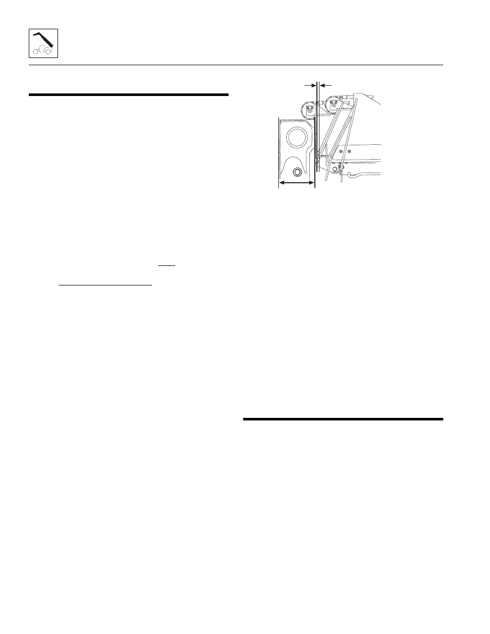
Adjust the retract chain as follows:
1. Fully retract the boom.
2. Measure the distance between the second boom
section and the third boom section (1). The
dimension should be 0.500 in, + 0.250 in - 0.0 in
(12,7 mm, + 6,75 mm - 0.0 mm).
3. Loosen the retract chain lock nut and adjusting nut
as far as possible.
4. Tighten the retract chain adjusting nut until the
proper distance is obtained and proper access hole
alignment is obtained.
5. Torque the lock nut to 100 lb-ft (135 Nm).
6. Recheck the extend chain adjustments and readjust
if necessary.
7. Measure the distance between the third boom
section and fourth boom section (2). The dimension
should be 18.5 in, + 0.25 in - 0.0 in
(469,9 mm, + 6,75 mm - 0,0 mm)
8. Tighten the retract chain adjusting nut until the
proper distance is obtained and proper access hole
alignment is obtained.
9. Torque the lock nuts to 100 lb-ft (135 Nm).
10. Re-adjust the extend chain as needed.
3.6
HYDRAULIC SUB-ASSEMBLY
REMOVAL/INSTALLATION
The hydraulic sub-assembly is located primarily in the
fourth boom section. It is fastened at the bottom front of
the fourth boom section and at the rear of the third boom
section.
3.6.1
Hydraulic Sub-Assembly Removal
1. Remove any attachment from the quick switch
assembly.
Note: Allow adequate room in front of the machine
when removing and installing the hydraulic sub-
assembly.
MY1320
1
2