2 assembling the hydraulic sub- assembly, 3 hydraulic sub-assembly installation, Assembling the hydraulic sub-assembly – JLG G12-55A AccuPlace Service Manual User Manual
Page 38: Hydraulic sub-assembly installation
Boom
3.16
G10-55A & G12-55A AccuPlace
3.6.2
Assembling the Hydraulic Sub-
Assembly
The following procedure is described with the assumption
that all components have been removed and assembly
proceeding from the beginning.
1. Place both sections on a suitable stand or support.
2. Install the wear pad to the bottom of the upper
hydraulic carrier.
3. Install the bulkhead fittings to each hydraulic carrier.
4. Install the tube assemblies to the bulkhead fittings
on each hydraulic carrier.
5. Install the cushion clamps to the tube assemblies
and secure to each hydraulic carrier.
6. Install the hose carrier to each hydraulic carrier and
install each tilt hose and auxiliary hose to the proper
fitting or tube connection.
7. Tie wrap the hydraulic hoses together where they
extend from each end of the hose carrier.
8. Fasten the two hydraulic carriers together using
plastic tie wraps or nylon straps for stability.
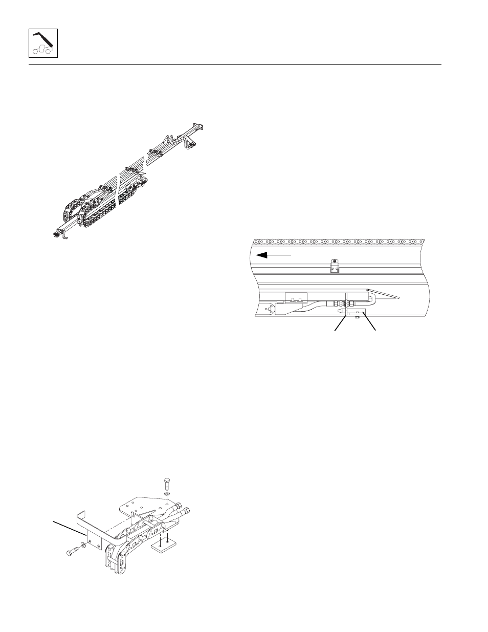
3.6.3
Hydraulic Sub-Assembly Installation
1. Clean and lubricate the side surfaces where the
hydraulic sub-assembly rides.
2. Install the guide bracket (1) on the front of the
hydraulic sub-assembly.
3. Fully collapse the hose carriers and secure together
using plastic tie wraps or nylon straps to keep them
from separating.
4. Install a sling around the balance point of the sub-
assembly. With a suitable lifting device, slowly insert
the sub-assembly into the front of the fourth boom
section.
5. Remove the first plastic tie wrap or nylon strap as the
hydraulic sub-assembly is being inserted into the
front of the fourth boom section.
6. Continue inserting the hydraulic sub-assembly and
removing the plastic tie wraps or nylon straps until
the sub-assembly is fully inserted into the boom.
7. Verify that the bottom bracket (2) on the sub-
assembly is in place on the bottom plate (3) of the
fourth boom section.
8. Install the cap screws, washers and nuts to the sub-
assembly bracket at the rear of the third boom
section.
9. Install both cap screws and locknuts to the sub-
assembly bracket at the front of the fourth boom
section.
10. Uncap and reconnect the previously labeled tilt and
auxiliary hydraulic hoses to the proper fittings at the
rear of the hydraulic sub-assembly.
11. Uncap and reconnect the previously labeled tilt and
auxiliary hydraulic hoses to the proper fittings at the
front of the fourth boom section.
12. If equipped, reconnect any electrical connections at
the front and rear of the boom assembly.
MY2730
MY2740
1
MY2700
3
FRONT
2