13 boom length sensor, Boom length sensor – JLG G12-55A AccuPlace Service Manual User Manual
Page 152
Electrical System
9.34
G10-55A & G12-55A AccuPlace
Right Side:
a. Right Side Boom Angle Sensor Removal
1. Park the machine on a firm, level surface, level the
machine, fully retract the boom, lower the boom,
place the transmission control lever in
(N) NEUTRAL, engage the park brake and shut the
engine OFF.
2. Place a Do Not Operate Tag on both the ignition key
switch and the steering wheel, stating that the
machine should not be operated.
3. Open engine cover. Allow system fluids to cool.
4. Disconnect the negative (-) battery cable at the
negative (-) battery terminal.
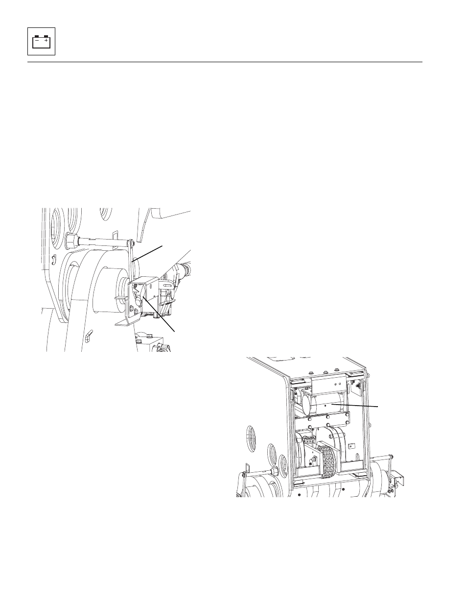
5. Unplug the wiring harness from the boom angle
sensor (3).
6. Remove the screw attaching the crank arm (4) to the
sensor shaft.
7. Remove the bolts holding the sensor to the sensor
cover.
8. Remove the boom angle sensor.
9. If necessary, remove the sensor cover from the
mounting bracket by removing the bolts.
b. Disassembly
1. Inspect the sensor and the wiring harness connector
terminals for continuity. Replace a defective or faulty
sensor with a new sensor.
c. Installation
1. Install the bolts holding the sensor to the sensor
cover.
2. Align the holes on the crank arm and sensor shaft
and install the screw to secure crank arm in place.
3. Connect the boom angle sensor to the wiring
harness.
4. Connect the negative (-) battery cable to the negative
(-) battery terminal.
5. Close and secure engine cover.
The sensor must be calibrated after installation. Refer to
Section 9.15.5, “Calibrations.”
9.11.13
Boom Length Sensor
The boom length sensor is a CAN-based cable reel that
measures the combined distance in which the extend/
retract cylinder and boom section three have moved.
The sensor is mounted at the rear of the boom.
a. Boom Length Sensor Removal
1. Park the machine on a firm, level surface, level the
machine, fully retract the boom, lower the boom,
place the transmission control lever in
(N) NEUTRAL, engage the park brake and shut the
engine OFF.
2. Place a Do Not Operate Tag on both the ignition key
switch and the steering wheel, stating that the
machine should not be operated.
3. Open engine cover. Allow system fluids to cool.
4. Disconnect the negative (-) battery cable at the
negative (-) battery terminal.
5. Unplug the wiring harness from the boom length
sensor (5).
6. Unhook the cable latch from the boom.
MAP0480
3
4
MAP0490
5