JLG G12-55A AccuPlace Service Manual User Manual
Page 131
9.13
G10-55A & G12-55A AccuPlace
Electrical System
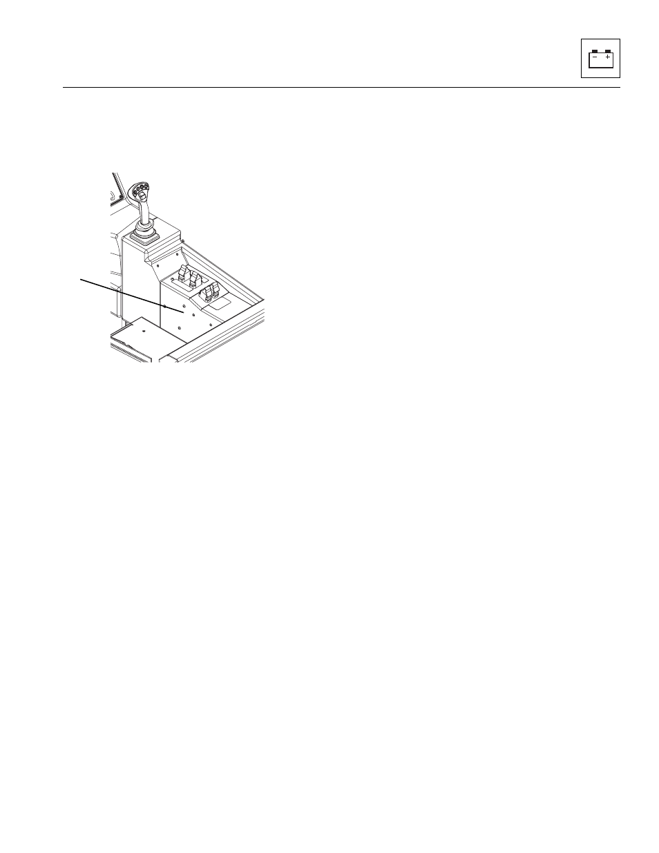
9.5.3
Frame Level, Auxiliary Hydraulic and
Outrigger Joysticks Module
The frame level, auxiliary hydraulic and outrigger
joysticks module is located on the inside of the right hand
side panel (4) where the joysticks are located.
a. Module Removal
1. Park the machine on a firm, level surface, level the
machine, fully retract the boom, lower the boom,
place the transmission control lever in
(N) NEUTRAL, engage the park brake and shut the
engine OFF.
2. Place a Do Not Operate Tag on both the ignition key
switch and the steering wheel, stating that the
machine should not be operated.
3. Open the engine cover. Allow the system fluids to
cool.
4. Disconnect the battery negative (-) cable from the
battery negative (-) terminal.
5. Remove the bolts securing the right hand side panel
to the cab. Refer to Section 4.3.5, “Frame Level,
Auxiliary Hydraulic and Outrigger Joysticks.”
6. Disconnect the electrical harnesses attached to the
module.
7. Remove the hardware securing the module to the
right hand side panel and remove the module.
b. Disassembly
DO NOT disassemble the module. The module is not
serviceable. Replace the module if found to be defective.
c. Inspection and Replacement
Inspect the module terminals for continuity. Replace the
module if continuity is not found.
d. Module Installation
1. Attach the module to the right hand side panel with
the previously removed hardware.
2. Reconnect the electrical harnesses to the module.
3. Install the right hand side panel to the cab with the
previously removed hardware. Refer to Section
4.3.5, “Frame Level, Auxiliary Hydraulic and
Outrigger Joysticks.”
4. Connect the negative (-) battery cable to the negative
(-) battery terminal.
5. Close and secure engine cover.
MAP0580
4