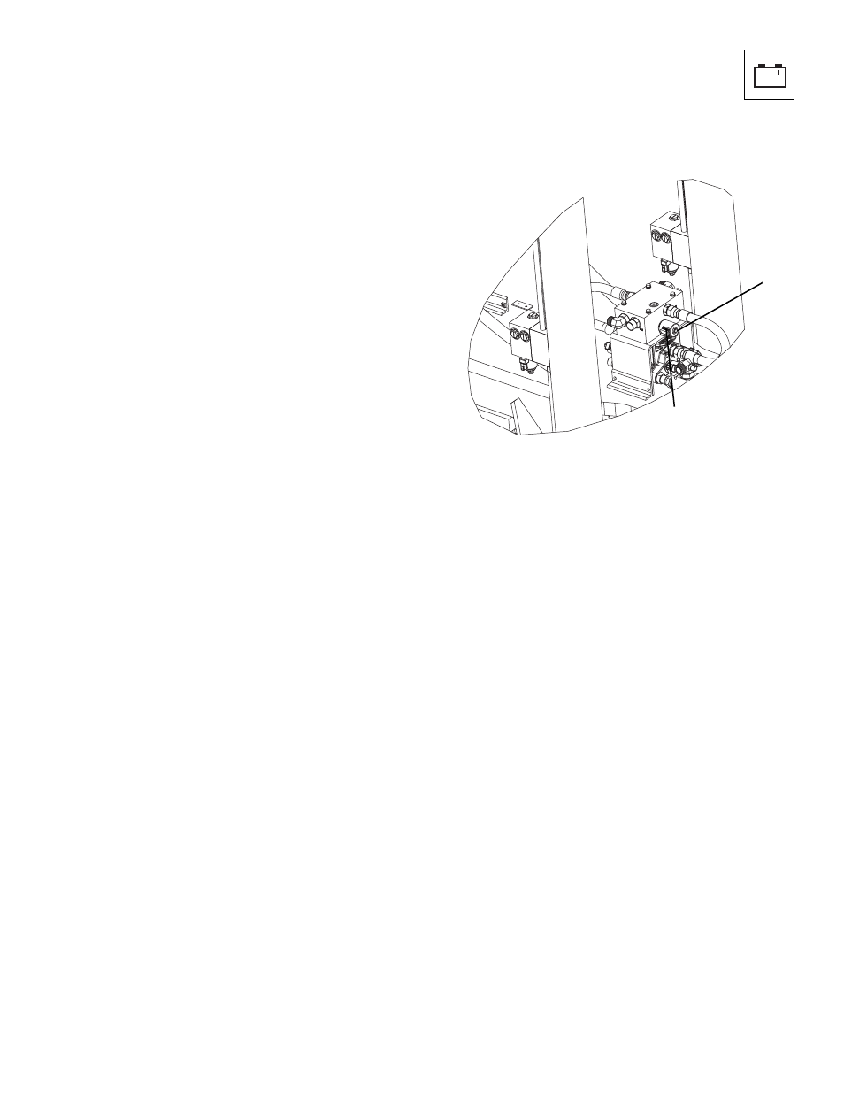
5 boom ride control solenoid valve, 6 lift isolation solenoid valves, Boom ride control solenoid valve – JLG G12-55A AccuPlace Service Manual User Manual
Page 147: Lift isolation solenoid valves
9.29
G10-55A & G12-55A AccuPlace
Electrical System
c. Pump Solenoid Valve Installation
Note: ALWAYS replace seals, o-rings, gaskets, etc.,
with new parts to help ensure proper sealing and
operation. Lubricate seals and o-rings with clean
hydraulic oil.
1. If necessary, install the pump solenoid in its original
orientation.
2. Slide the pump coil over the solenoid. Tighten the
nut to secure the solenoid. DO NOT overtighten.
3. Connect the wiring connector to the pump coil lead.
4. Connect the battery negative (-) cable at the battery
negative (-) terminal.
5. Close and secure the engine cover.
9.11.5
Boom Ride Control Solenoid Valve
a. Boom Ride Control Solenoid Valve Removal
1. Park the machine on a firm, level surface, level the
machine, fully retract the boom, lower the boom,
place the transmission control lever in
(N) NEUTRAL, engage the park brake and shut the
engine OFF.
2. Place a Do Not Operate Tag on both the ignition key
switch and the steering wheel, stating that the
machine should not be operated.
3. Open the engine cover. Allow the system fluids to
cool.
4. Disconnect the battery negative (-) cable from the
battery negative (-) terminal.
5. Disconnect the wiring connector at the boom ride
control solenoid lead.
6. Remove the nut on the end of the boom ride control
coil (7).
7. Remove the boom ride control coil.
8. Remove the boom ride control solenoid (8).
(Remove only if the electrical coil is found to not be
faulty.)
b. Disassembly
DO NOT disassemble the solenoid. The solenoid is not
serviceable. Replace solenoid if found to be defective.
c. Boom Ride Control Solenoid Valve Installation
Note: ALWAYS replace seals, o-rings, gaskets, etc.,
with new parts to help ensure proper sealing and
operation. Lubricate seals and o-rings with clean
hydraulic oil.
1. If necessary, install the boom ride control solenoid in
its original orientation.
2. Slide the boom ride control coil over the solenoid.
Tighten the nut to secure the solenoid. DO NOT
overtighten.
3. Connect the wiring connector to the boom ride
control coil lead.
4. Connect the battery negative (-) cable at the battery
negative (-) terminal.
5. Close and secure the engine cover.
9.11.6
Lift Isolation Solenoid Valves
a. Lift Isolation Solenoid Valve Removal
1. Park the machine on a firm, level surface, level the
machine, fully retract the boom, lower the boom,
place the transmission control lever in
(N) NEUTRAL, engage the park brake and shut the
engine OFF.
MAP0450
7
8