11 valve controllers, 9 hydraulic piston accumulator, 1 accumulator removal – JLG G12-55A AccuPlace Service Manual User Manual
Page 112: Hydraulic piston accumulator, Valve controllers, Accumulator removal, Caution
Hydraulic System
8.22
G10-55A & G12-55A AccuPlace
8.8.11
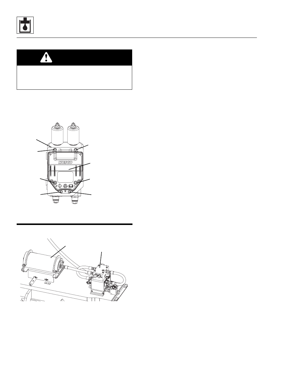
Valve Controllers
Valve controllers (7) are located on the following valves:
Lift Valve, ISP Valve, Telescope Valve and Tilt Valve.
When installing the valve controller onto the valve, ensure
transducer gaskets are in place and torque the bolts to 4
lb-ft (5 Nm) in the following sequence:
8.9
HYDRAULIC PISTON
ACCUMULATOR
8.9.1
Accumulator Removal
1. Park the machine on a firm, level surface, level the
machine, fully retract the boom, raise and support the
boom, place the transmission control lever in (N)
NEUTRAL, engage the park brake and shut the
engine OFF.
2. Place a Do Not Operate Tag on both the ignition key
switch and the steering wheel, stating that the
machine should not be operated.
3. Open the engine cover. Allow the system fluids to
cool.
4. Disconnect the battery negative (-) cable from the
battery negative (-) terminal.
5. Thoroughly clean the accumulator and surrounding
area, including all hoses and fittings before
proceeding.
6. Discharge the pressure in the accumulator.
Note: Attaching the charging assembly to the gas valve
on the accumulator will relieve any residual pressure in
the accumulator. Refer to Section 8.9.2, “Accumulator
Pre-Charge & Check Procedure.”
7. Place a suitable container under the hydraulic hose
fittings on the accumulator and lift manifold to catch
hydraulic oil.
8. Label, disconnect and cap the hydraulic hose
attached to the accumulator (1) and lift manifold (2).
Cap all fittings to prevent dirt & debris from entering
the hydraulic system.
9. Label and disconnect the electrical connectors from
the accumulator.
10. Remove the hardware securing the accumulator to
the bracket. Attach a suitable sling to the
accumulator. Remove the accumulator from the
machine.
Note: Accumulator weighs approximately
128 lbs (58 kg).
e. Accumulator Installation
Note: New accumulators are precharged.
1. Install the accumulator to the bracket with the
previously used hardware.
2. If necessary, charge the accumulator. Refer to
Section 8.9.2, “Accumulator Pre-Charge & Check
Procedure.”
3. Uncap and connect the previously labeled hydraulic
hose to the appropriate locations on the accumulator
and lift manifold.
4. Connect the previously labeled electrical connectors
to the accumulator.
5. Connect the battery negative (-) cable to the battery
negative (-) terminal.
CAUTION
HIGH OIL PRESSURE WITHIN VALVE AND
CONTROLLER. Removing the controller may cause
cylinder leakage. Brace and block the boom before
removing lift valve and telescope valve controllers.
MAP0630
6
2
4
5
3
1
Valve Controller
Valve
MAP0430
1
2