7 service brake valve, 8 brake test, To section 8.8.8, “brake test – JLG G12-55A AccuPlace Service Manual User Manual
Page 109: Section 8.8.8, “brake, Test, Service brake valve, Brake test
8.19
G10-55A & G12-55A AccuPlace
Hydraulic System
5. Uncap and connect the previously labeled hydraulic
hoses to their appropriate locations.
6. Connect the previously labeled electrical connectors
to the tilt valve.
7. Connect the battery negative (-) cable to the battery
negative (-) terminal.
8. Before starting the machine, check fluid level of the
hydraulic fluid reservoir and if necessary fill to full
mark with Mobilfluid 424
®
(ISO 46).
9. Start the machine and run at low idle for about one
minute. Test the functions of the tilt cylinder.
10. Inspect for leaks and check level of hydraulic fluid in
reservoir. Add hydraulic fluid if needed. Shut the
engine OFF.
11. Close and secure the engine cover.
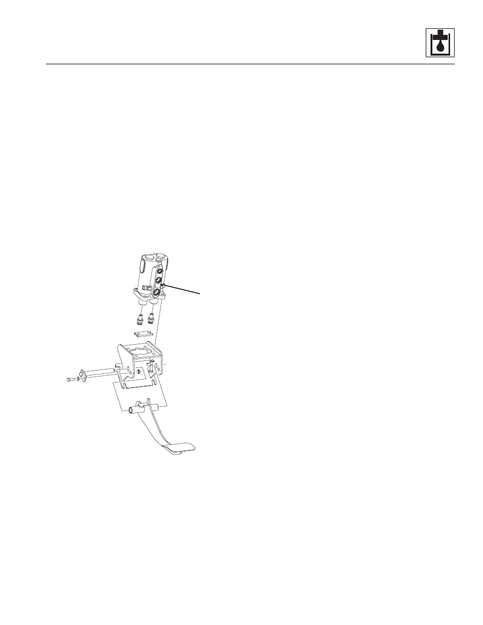
8.8.7
Service Brake Valve
a. Service Brake Valve Removal
1. Park the machine on a firm, level surface, level the
machine, fully retract the boom, lower the boom,
place the transmission control lever in (N) NEUTRAL,
engage the park brake and shut the engine OFF.
2. Place a Do Not Operate Tag on both the ignition key
switch and the steering wheel, stating that the
machine should not be operated.
3. Open the engine cover. Allow the system fluids to
cool.
4. Disconnect the battery negative (-) cable from the
battery negative (-) terminal.
5. Label, disconnect and cap all hoses attached to the
Service Brake valve (13).
6. Remove the service brake pedal. Refer to Section
7. Remove the capscrews, nuts and lockwashers
mounting the service brake valve to the service
brake bracket.
Note: DO NOT disassemble the service brake valve.
The service brake valve is not serviceable and must be
replaced in its entirety, if defective.
b. Service Brake Valve Installation
1. Install the service brake valve with the capscrews,
lockwashers and nuts onto the service brake
bracket.
2. Install the service brake pedal. Refer to Section
Note: ALWAYS replace seals, o-rings, gaskets, etc.,
with new parts to help ensure proper sealing and
operation. Lubricate seals and o-rings with clean
hydraulic oil.
3. Use new oiled o-rings as required. Uncap and
connect the previously labeled hoses to the service
brake valve.
4. Check the routing of all hoses, and tubing for sharp
bends or interference with any rotating members,
and install tie wraps and/or protective conduit as
required. Tighten all tube and hose clamps.
5. Connect the battery negative (-) cable to the battery
negative (-) terminal.
6. Start the engine and run at approximately one-third
to one-half throttle for about one minute, without
moving the machine or operating any hydraulic
functions.
7. Inspect the service brake valve and connections for
leaks, and check the level of the hydraulic fluid in the
reservoir. Shut the engine OFF.
Note: Check for leaks, and repair as required before
continuing. Add hydraulic fluid to the reservoir as
needed.
8. Wipe up any hydraulic fluid spillage in, on, near and
around the machine, work area and tools.
8.8.8
Brake Test
Carefully bleed the brake lines as soon as the brake valve
is installed in the machine. Air in the system will not allow
MAP0270
13