6 tilt valve, Tilt valve – JLG G12-55A AccuPlace Service Manual User Manual
Page 108
Hydraulic System
8.18
G10-55A & G12-55A AccuPlace
8. If necessary, remove the telescope valve controller
from the telescope valve.
b. Telescope Valve Installation
1. If necessary, install the telescope valve controller to
the telescope valve with the previously used
hardware. Refer to Section 8.8.11, “Valve
Controllers,” for proper torque values and sequence.
2. Install the telescope valve to the extend cylinder with
the previously used hardware.
3. Connect the previously labeled electrical connectors
to the telescope valve.
4. Uncap and connect the previously labeled hydraulic
hoses to their appropriate locations.
5. Connect the battery negative (-) cable to the battery
negative (-) terminal.
6. Before starting the machine, check fluid level of the
hydraulic fluid reservoir and if necessary fill to full
mark with Mobilfluid 424
®
(ISO 46).
7. Start the machine and run at low idle for about one
minute. Test the functions of the telescope valve.
8. Inspect for leaks and check level of hydraulic fluid in
reservoir. Add hydraulic fluid if needed. Shut the
engine OFF.
9. Close and secure the engine cover.
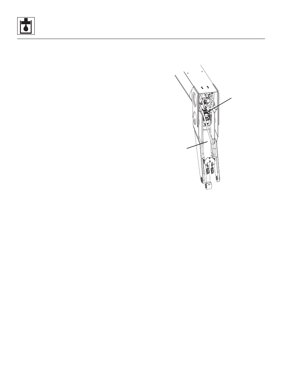
8.8.6
Tilt Valve
a. Tilt Valve Removal
1. Park the machine on a firm, level surface, level the
machine, fully retract the boom, lower the boom,
place the transmission control lever in (N) NEUTRAL,
engage the park brake and shut the engine OFF.
2. Place a Do Not Operate Tag on both the ignition key
switch and the steering wheel, stating that the
machine should not be operated.
3. Open the engine cover. Allow the system fluids to
cool.
4. Disconnect the battery negative (-) cable from the
battery negative (-) terminal.
5. Remove the protective cover from the boomhead.
6. Thoroughly clean the valve and surrounding area,
including all hoses and fittings before proceeding.
7. Label, disconnect and cap the hydraulic hoses
attached to the tilt cylinder (11). Cap all fittings to
prevent dirt & debris from entering the hydraulic
system.
8. Label and disconnect the electrical connectors from
the tilt valve (12).
9. Attach a suitable sling to an appropriate lifting device
and to the tilt cylinder. Make sure the device used is
capable of supporting the cylinder.
10. Remove the lock bolt and/or any retaining clips
securing the cylinder pins. Remove the cylinder pins.
11. Lower the cylinder from the boom.
12. Remove the hardware securing the Tilt valve to the
tilt cylinder. Remove the tilt valve.
13. If necessary, remove the tilt valve controller from the
tilt valve.
b. Tilt Valve Installation
1. If necessary, install the tilt controller to the tilt valve
with the previously used hardware. Refer to Section
8.8.11, “Valve Controllers,” for proper torque values
and sequence.
2. Install the tilt valve to the tilt cylinder with the
previously used hardware.
3. Grease the bushings at the ends of the tilt cylinder.
Using an appropriate sling, lift the cylinder into it’s
mounting position.
4. Align the cylinder bushing and install pin and
retaining clips.
MAP0260
12
11