2 isp valve, Isp valve – JLG G12-55A AccuPlace Service Manual User Manual
Page 105
8.15
G10-55A & G12-55A AccuPlace
Hydraulic System
5. Thoroughly clean the valve and surrounding area,
including all hoses and fittings before proceeding.
6. Label, disconnect and cap the hydraulic hoses
attached to the lift valve (1) and lift manifold (2). Cap
all fittings to prevent dirt & debris from entering the
hydraulic system.
7. Label and disconnect the electrical connectors from
the lift valve.
8. Support the underside of the lift valve and remove
the bolts (3) securing the lift manifold and lift valve to
the bracket. Carefully remove the lift valve and lift
manifold from the bracket.
9. If necessary, remove the hardware securing the
bracket to the machine frame.
10. If necessary, remove the lift valve controller from the
lift valve.
b. Lift Valve Installation
1. If necessary, install the lift valve controller to the lift
valve with the previously used hardware. Refer to
Section 8.8.11, “Valve Controllers,” for proper torque
values and sequence.
2. If necessary, Install the bracket onto the machine
frame with the previously used hardware.
3. Place the lift manifold on the top of the bracket and
insert the previously removed bolts. Place the lift
valve on the underside of the bracket and secure
with the four bolts.
4. Uncap and connect the previously labeled hydraulic
hoses to their appropriate locations.
5. Connect the previously labeled electrical connectors
to the lift valve.
6. Connect the battery negative (-) cable to the battery
negative (-) terminal.
7. Before starting the machine, check fluid level of the
hydraulic fluid reservoir and if necessary fill to full
mark with Mobilfluid 424
®
(ISO 46).
8. Start the machine and run at low idle for about one
minute. Test the functions of the lift valve.
9. Inspect for leaks and check level of hydraulic fluid in
reservoir. Add hydraulic fluid if needed. Shut the
engine OFF.
10. Close and secure the engine cover.
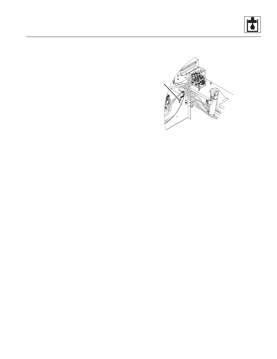
8.8.2
ISP Valve
a. ISP Valve Removal
1. Park the machine on a firm, level surface, level the
machine, fully retract the boom, lower the boom,
place the transmission control lever in (N) NEUTRAL,
engage the park brake and shut the engine OFF.
2. Place a Do Not Operate Tag on both the ignition key
switch and the steering wheel, stating that the
machine should not be operated.
3. Open the engine cover. Allow the system fluids to
cool.
4. Disconnect the battery negative (-) cable from the
battery negative (-) terminal.
5. Thoroughly clean the valve and surrounding area,
including all hoses and fittings before proceeding.
6. Label, disconnect and cap the hydraulic hoses
attached to the ISP valve (4). Cap all fittings to
prevent dirt & debris from entering the hydraulic
system.
7. Label and disconnect the electrical connector from
the ISP valve controller.
8. Remove the hardware securing the ISP valve to the
engine compartment.
9. If necessary, remove the ISP valve controller from
the ISP valve.
b. ISP Valve Installation
1. If necessary, install the ISP valve controller to the
ISP valve with the previously used hardware. Refer
to Section 8.8.11, “Valve Controllers,” for proper
torque values and sequence.
2. Install the ISP valve to the engine compartment with
the previously used hardware.
3. Connect the previously labeled electrical connector
to the ISP valve controller.
MAP0240
4