JLG G12-55A AccuPlace Service Manual User Manual
Page 170
Electrical System
9.52
G10-55A & G12-55A AccuPlace
SYSTEM POWER: ENGINE RPM:
XXXX
Engine RPM reported from engine controller.
ENGINE STATE:
OFF/CRANKING/
RUNNING/
UNKNOWN
Reports state of engine depending on RPM value.
ENGINE OIL PRESS:
XXX PSI
Engine oil pressure reported from engine
controller.
ENGINE TEMP:
XXX DEG C
Engine temperature reported from engine
controller.
UGM V BAT:
XX.XV
UGM battery voltage.
ISP V BAT:
XX.XV
Battery voltage reported from ISP.
LIFT V BAT:
XX.XV
Battery voltage reported from Lift valve.
TELE V BAT:
XX.XV
Battery voltage reported from Tele valve.
FORK V BAT:
XX.XV
Battery voltage reported from Fork valve.
SYSTEM:
CHASSIS TILT X:
±XX.X DEG
Displays X side-to-side tilt angle.
CHASSIS TILT Y:
±XX.X DEG
Displays Y fore-to-aft tilt angle.
BOOM MODE
STANDARD/
ACCUPLACE
Displays whether joystick is mapped to provide
boom motion as a standard Telehandler or
coordinated AccuPlace.
ELEV STATUS:
ABOVE/BELOW
Displays Elevation status.
TRANSPORT MODE: IN TRANSPORT/
OUT OF
TRANSPORT
Displays whether Boom is in Transport Mode.
BOOM RIDE MODE:
#
ON/OFF
If configured, displays status of Boom Ride Mode.
BOOM SPEED:
LOW, MED,
NORMAL,
EMERGENCY
LOWER, DISABLED
Boom speed set via INCOVA configuration
message.
INCOVA CFG LSB:
2
XX XX XX XX
Bytes 1-4 of INCOVA Configuration Message.
INCOVA CFG MSB:
2
XX XX XX XX
Bytes 5-8 of INCOVA Configuration Message.
RETRIEVAL LOCK:
2
ACTIVE/NOT
ACTIVE
Displays status of boom Retrieval Lock.
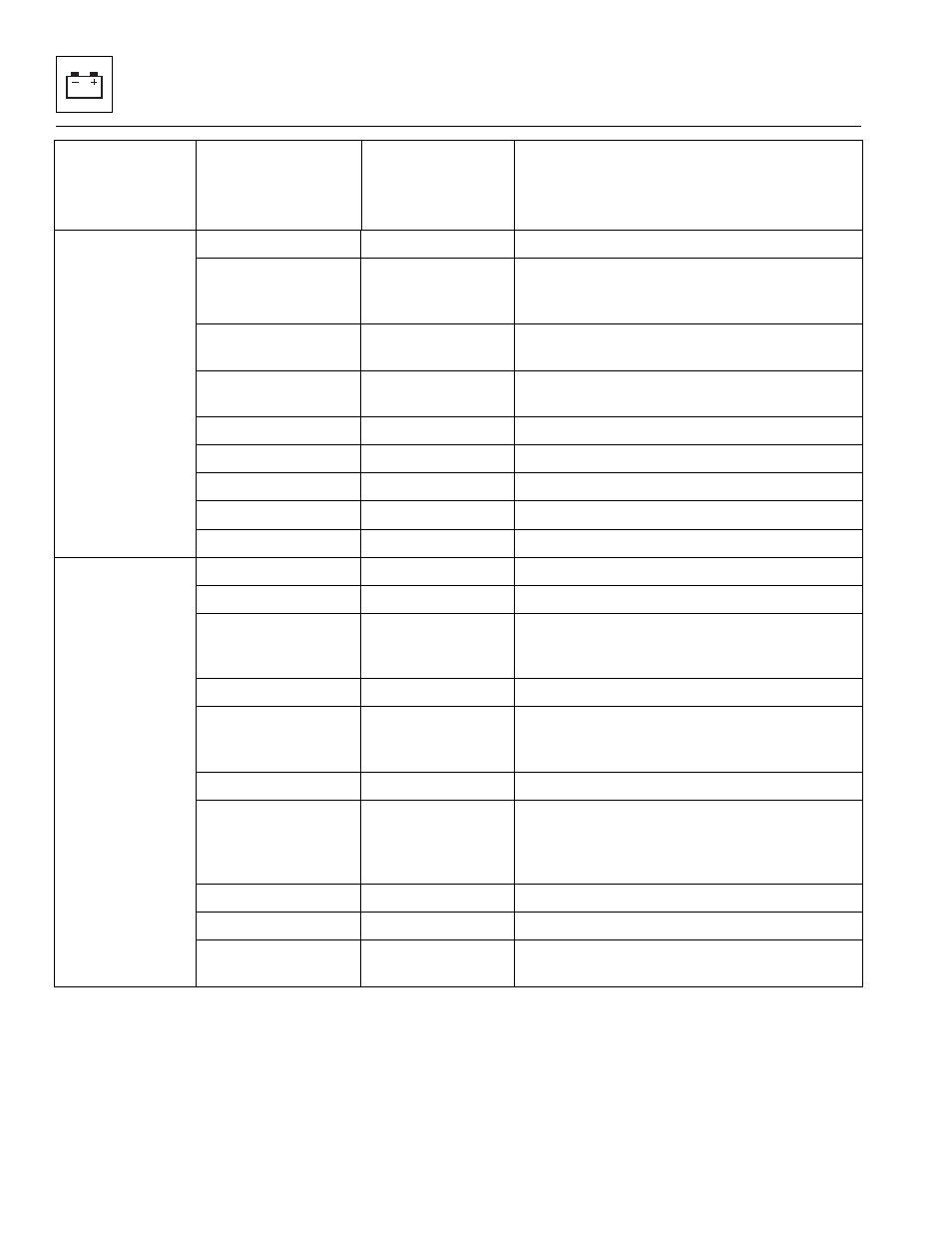
Diagnostics
Submenu
(Displayed on
Analyzer 1
st
Line)
Parameter
(Displayed on
Analyzer 1
st
Line)
Parameter Value
(Displayed on
Analyzer 2
nd
Line)
Description