2 cylinder pressure checking, 3 steering cylinders, Cylinder pressure checking – JLG G12-55A AccuPlace Service Manual User Manual
Page 116: Steering cylinders
Hydraulic System
8.26
G10-55A & G12-55A AccuPlace
6. Carefully insert the cylinder rod assembly into the
cylinder barrel.
7. Screw the head gland into the cylinder barrel and
tighten with a spanner wrench. Refer to Section
8.10.4, “Cylinder Torque Specifications” for torque
specifications for the head gland.
8. If applicable, install new counter balance valve into
block on the cylinder barrel.
e. General Cylinder Installation
1. Grease the bushings at the ends of the hydraulic
cylinder. Using an appropriate sling, lift the cylinder
into it’s mounting position.
2. Align cylinder bushing and install pin, lock bolt or
retaining clip.
3. Connect the hydraulic hoses in relation to the labels
or markings made during removal.
4. Before starting the machine, check fluid level of the
hydraulic fluid reservoir and if necessary fill to full
mark with Mobilfluid 424
®
(ISO 46).
5. Start the machine and run at low idle for about one
minute. Slowly activate hydraulic cylinder function in
both directions allowing cylinder to fill with hydraulic
oil.
6. Inspect for leaks and check level of hydraulic fluid in
reservoir. Add hydraulic fluid if needed. Shut the
engine OFF.
7. Wipe up any hydraulic fluid spillage in, on, near and
around the machine, work area and tools.
8. Close and secure the engine cover.
8.10.2
Cylinder Pressure Checking
Attach a 5000 psi (345 bar) gauge to the test ports on the
hydraulic pump manifold to check the system pressure.
For more information, refer to Section 8.3.1, “Pressure
Checks and Adjustments,” and Section 8.4.1, “Hydraulic
Pressures.”
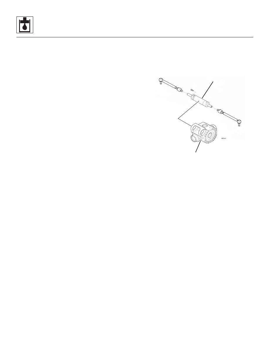
8.10.3
Steering Cylinders
The steer cylinder is attached to each axle center
housing.The steer cylinder assembly can be found in
Section 5.3, “Axle Assemblies.” The steer cylinder is
covered in the appropriate manufacturer’s axle literature.
Axle Center Section
Steering Cylinder