3 stabilizer valve, Stabilizer valve – JLG G12-55A AccuPlace Service Manual User Manual
Page 106
Hydraulic System
8.16
G10-55A & G12-55A AccuPlace
4. Uncap and connect the previously labeled hydraulic
hoses to their appropriate locations.
5. Connect the battery negative (-) cable to the battery
negative (-) terminal.
6. Before starting the machine, check fluid level of the
hydraulic fluid reservoir and if necessary fill to full
mark with Mobilfluid 424
®
(ISO 46).
7. Start the machine and run at low idle for about one
minute. Test the functions of the ISP valve.
8. Inspect for leaks and check level of hydraulic fluid in
reservoir. Add hydraulic fluid if needed. Shut the
engine OFF.
9. Close and secure the engine cover.
8.8.3
Stabilizer Valve
a. Stabilizer Valve Removal
1. Park the machine on a firm, level surface, level the
machine, fully retract the boom, lower the boom,
place the transmission control lever in (N) NEUTRAL,
engage the park brake and shut the engine OFF.
2. Place a Do Not Operate Tag on both the ignition key
switch and the steering wheel, stating that the
machine should not be operated.
3. Open the engine cover. Allow the system fluids to
cool.
4. Disconnect the battery negative (-) cable from the
battery negative (-) terminal.
5. Thoroughly clean the valve and surrounding area,
including all hoses and fittings before proceeding.
6. Remove the valve protective cover from the machine
frame.
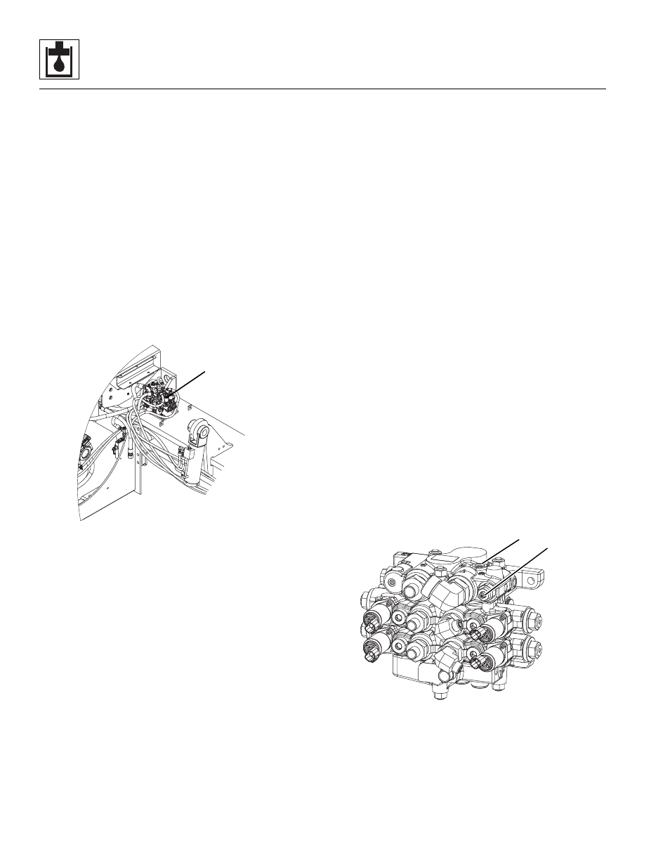
7. Label, disconnect and cap the hydraulic hoses
attached to the stabilizer valve (5). Cap all fittings to
prevent dirt & debris from entering the hydraulic
system.
8. Label and disconnect the electrical connectors from
the stabilizer valve.
9. Remove the hardware securing the stabilizer valve
to the machine frame.
b. Stabilizer Valve Installation
1. Install the stabilizer valve to the machine frame with
the previously used hardware.
2. Connect the previously labeled electrical connectors
to the stabilizer valve.
3. Uncap and connect the previously labeled hydraulic
hoses to their appropriate locations.
4. Connect the battery negative (-) cable to the battery
negative (-) terminal.
5. Before starting the machine, check fluid level of the
hydraulic fluid reservoir and if necessary fill to full
mark with Mobilfluid 424
®
(ISO 46).
6. Start the machine and run at low idle for about one
minute. Test the functions of the stabilizer valve.
7. Inspect for leaks and check level of hydraulic fluid in
reservoir. Add hydraulic fluid if needed. Shut the
engine OFF.
8. Close and secure the engine cover.
c. Stabilizer Valve Adjustment
If slow motion is experienced on one of the stabilizers/
outriggers after one of the two stabilizers/outriggers hits
end of stroke, use the following procedure to adjust the
stabilizer valve:
1. Extend one stabilizer/outrigger to end of stroke.
2. Measure the pressure at the valve LS port (7).
3. Adjust the load sense relief valve screw (6) until the
measured pressure is 325 psi (22 bar) below system
pressure (nominally 3300 psi (228 bar)) as read via
the analyzer under DIAGNOSTICS/ISP.
MAP0240
5
MAP0730
6
7