4 cab removal, Cab removal, Warning – JLG G12-55A AccuPlace Service Manual User Manual
Page 51
4.7
G10-55A & G12-55A AccuPlace
Cab and Covers
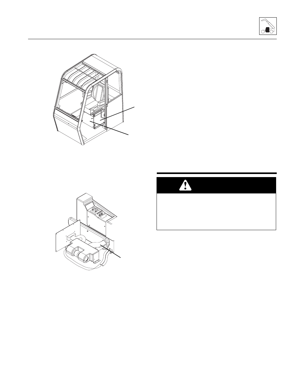
9. Remove the bolts that secure the seat to the cab.
Remove the seat.
10. Remove the bolts securing the front plate (11) to the
seat riser weldment (12).
11. Remove the bolts securing the seat riser weldment
to the cab. Remove the riser weldment.
12. Loosen the hose clamps, label and disconnect the
heater hoses (13). Cap or plug the hoses to prevent
debris from entering the heater system.
13. Label and disconnect any electrical connections.
14. Remove the bolts securing the heater assembly to
the cab. Remove the heater assembly.
b. Heater Assembly Installation
1. Position the heater assembly to its original orientation
in the cab. Secure with the previous hardware.
2. Connect the previously labeled electrical
connections.
3. Connect the previously labeled heater hoses to their
appropriate locations.
4. Install the seat riser weldment.
5. Install the front plate to the seat riser weldment.
6. Install the cab seat.
7. Fill the cooling system completely with a 50/50
mixture of ethylene glycol and water, allowing time
for the coolant to fill the engine block. The cooling
system capacity is listed in Section 2.4, “Fluid and
Lubricant Capacities.”
8. Connect the battery negative (-) cable to the battery
negative (-) terminal.
Note: When the engine is initially started, run it briefly at
low idle and check the machine for any visual sign of
fluid leakage. STOP the engine immediately if any
leakage is noted, and make any necessary repairs
before continuing.
9. Wait for the engine to cool and check the coolant
level. Add coolant as required to bring the coolant to
the proper level.
4.4
CAB REMOVAL
Note: To help ensure safety and optimum performance,
replace the cab if it is damaged. Refer to the appropriate
parts manual for ordering information.
Inspect the cab, its welds and mounts. If modification,
damage, a cracked weld and/or fatigued metal is
discovered, replace the cab. Contact the JLG distributor or
the JLG Service Department with any questions about
the suitability or condition of a cab.
Note: Remove and label cab components as needed
before removing the cab from the machine. Label,
disconnect and cap hydraulic hoses. Transfer cab parts
to the replacement cab after the replacement cab is
securely mounted on the machine.
1. Park the machine on a firm, level surface. Allow
sufficient overhead and side clearance for cab
removal. Level the machine, fully retract the boom,
lower the boom, place the travel select lever in the
(N) NEUTRAL position, engage the park brake and
shut the engine OFF.
MY0190
11
12
MY2790
13
WARNING
The protection offered by this ROPS/FOPS will be
impaired if subjected to any modification or structural
damage, at which time replacement is necessary.
ROPS/FOPS must be properly installed using
fasteners of correct size and grade, and torqued to
their specified value.