JLG G12-55A AccuPlace Service Manual User Manual
Page 128
Electrical System
9.10
G10-55A & G12-55A AccuPlace
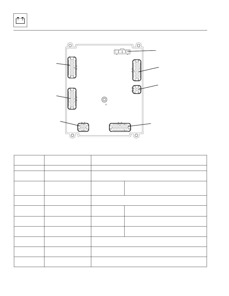
e. UGM Connections
a. UGM Inputs
MAP0540
J3
J4
J2
J1
J8
J12
J7
UGM
Connector/Pin
Description
Description/Purpose
J3-2
Sway Valve Return
Current feedback return for Sway Left and Right Solenoids
J3-6
Right Stabilizer Valve
Return
Current feedback return for Right Up and Down Solenoids
J3-13
Boom Angle Right
Sensor Signal
Analog Input
Signal Range: 0.5 – 4.5V
0.5V = 0°
4.5V = 90°
J3-14
Left Stabilizer Valve
Return
Current feedback return for Left Up and Down Solenoids
J4-6
AccuPlace Mode Fault
Reset Switch
High Sensing
Digital Input
Closed = V
bat
= Request to Reset Fault to
Continue Motion
J4-10
Sway Joystick Out of
Neutral
High Sensing
Digital Input
Closed = V
bat
= Out of Neutral
J4-11
Aux Joystick Out of
Neutral
High Sensing
Digital Input
Closed = V
bat
= Out of Neutral
J4-18
Boom Ride Enable
Switch
Closed = V
bat
= Request for Boom Ride Mode
J4-23
Right Stabilizer Joystick
Out of Neutral
Closed = V
bat
= Out of Neutral
J4-30
Continuous Auxiliary
Hydraulics Switch
Closed = V
bat
= Request for Boom Ride Mode