JLG G12-55A AccuPlace Service Manual User Manual
Page 52
Cab and Covers
4.8
G10-55A & G12-55A AccuPlace
2. Block all four wheels to help prevent the machine
from moving. Ensure that there is sufficient overhead
and side clearance for cab removal.
3. Open the engine cover. Allow the system fluids to
cool.
4. Disconnect the battery negative (-) cable at the
battery negative (-) terminal.
5. Place a funnel at the base of the radiator to channel
the drained coolant into the container. Loosen the
drain petcock and allow the coolant to drain.
6. Transfer the coolant to a container with a cover, and
label as “Used Antifreeze.” Dispose of the used
coolant at an approved recycling facility.
7. Tighten the radiator drain petcock.
8. Disconnect the cab heater hoses. Refer to Section
4.3.7, “Heater/Defroster System (If equipped).”
9. Remove the necessary dash panels to gain access
to the electrical wiring connections. Label and
disconnect the harnesses. Push the harness
connectors through the opening in the cab.
10. Remove the boom joystick from the mounting
position. Refer to Section 4.3.4, “Boom Joystick
Assembly.” Label and disconnect the electrical
harness attached to the boom joystick.
11. Remove the frame level and attachment tilt and
auxiliary hydraulic joysticks. Refer to Section 4.3.5,
“Frame Level, Auxiliary Hydraulic and Outrigger
Joysticks.” Label and disconnect the electrical
harnesses attached to the joysticks.
12. Label, disconnect and cap all hydraulic hoses
attached to the steering orbitrol valve. Cap all fittings
and openings to keep dirt and debris from entering
the hydraulic system.
13. Label, disconnect and cap all hydraulic hoses
attached to the steering orbitrol valve. Cap all fittings
and openings to keep dirt and debris from entering
the hydraulic system.
14. Label, disconnect and cap all hydraulic hoses
attached to the service brake valve. Cap all fittings
and openings to keep dirt and debris from entering
the hydraulic system.
15. Push all the hydraulic hoses through the opening in
the cab.
16. Disconnect the throttle cable from the throttle
assembly. Refer to Section 4.3.3, “Throttle Pedal.”
17. Disconnect the engine air filter and hydraulic oil
reservoir breather from their brackets at the top of
the cab. Move the air filter and breather clear from
the cab so they do not become damaged during cab
removal.
18. Remove the fuel tank from the cab. Refer to Section
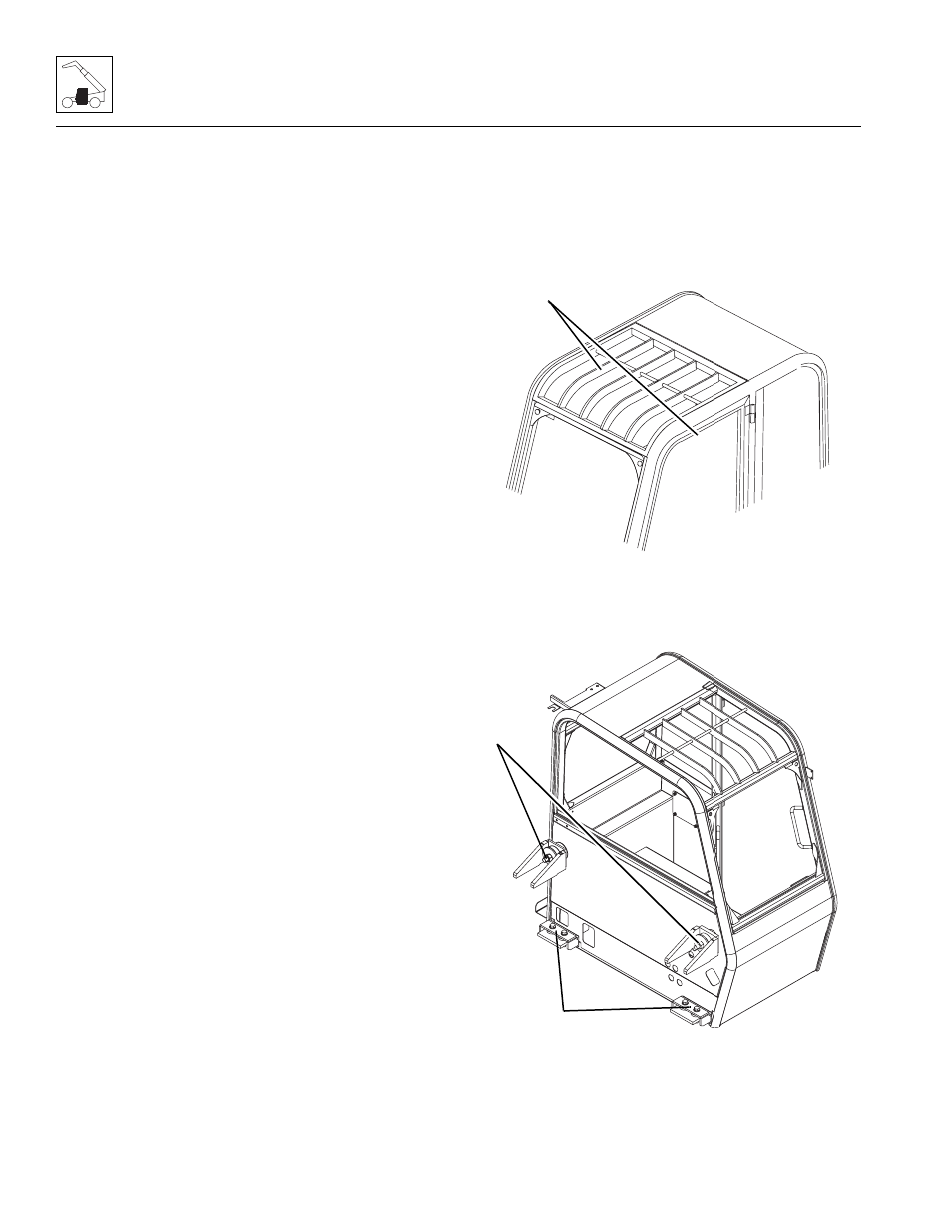
19. Route a sling with a suitable lifting capacity under
the inner six braces (14) and behind the center cross
support above the wind shield.
20. Remove the two cab side-mount bolts, washers,
isolators and nuts (15) in the cab.
21. Remove the four lower cab-to-frame bolts, washers
and nuts (16).
22. Remove the mirrors and all other cab components
as needed, if not previously removed.
23. Carefully begin to lift the cab. Stop and check that all
wiring, hydraulic hoses and fasteners are
disconnected or removed.
MY0610
14
MAP0160
15
16