JLG G12-55A AccuPlace Service Manual User Manual
Page 174
Electrical System
9.56
G10-55A & G12-55A AccuPlace
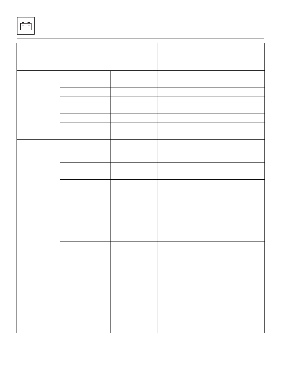
CAN
STATISTICS
2
CAN1 RX/S:
XXXXX
CAN1 Receptions per second by UGM.
CAN1 TX/S:
XXXXX
CAN1 Transmissions per second by UGM.
CAN1 BUS PASS:
XXXXX
CAN1 passive messages; rolls over at 65535.
CAN1 ERR F/S:
XXXXX
CAN1 errors frames per second.
CAN2 RX/S:
XXXXX
CAN2 Receptions per second by UGM.
CAN2 TX/S:
XXXXX
CAN2 Transmissions per second by UGM.
CAN2 BUS PASS:
XXXXX
CAN2 passive messages; rolls over at 65535.
CAN2 ERR F/S:
XXXXX
CAN2 errors frames per second
DATALOG:
DATALOG:
ON XXXXH XXM
Displays total controller on (power) time.
DATALOG:
ENGINE XXXXH
XXM
Displays time engine running.
DATALOG:
LIFT XXXXH XXM
Displays total controller lift operation time.
DATALOG:
TELE XXXXH XXM
Displays total controller telescope operation time.
DATALOG:
FORK XXXXH XXM
Displays total controller for operation time.
DATALOG:
AUX HYD XXXXH
XXM
Displays total auxiliary hydraulics 1 and 2
operation time.
DATALOG: UGM
DATALOG: ISP
DATALOG: LIFT
DATALOG: TELE
DATALOG: FORK
MAX VOLTS XX.XV Displays maximum measured battery voltage for
UGM, ISP, and all INCOVA modules.
DATALOG: ISP
DATALOG: LIFT
DATALOG: TELE
DATALOG: FORK
MAX OIL ±XXXC
Maximum oil temp measured on INCOVA Valve
with associated valve name (i.e., Lift, Tele, Fork,
etc.).
DATALOG: LIFT
CYCLES XXXXXX
Number of cycles on Lift; Lift cycle defined as Lift
Up knowing that complementary Lift Down must
naturally happen as part of a cycle.
DATALOG: TELE
CYCLES XXXXXX
Number of cycles on Tele; Tele cycle defined as
Tele Out knowing that complementary Tele In
must naturally happen as part of a cycle.
DATALOG: FORK
CYCLES XXXXXX
Number of cycles on Fork; Fork cycle defined as
Fork Tilt Up knowing that complementary Fork Tilt
Down must naturally happen as part of a cycle.
Diagnostics
Submenu
(Displayed on
Analyzer 1
st
Line)
Parameter
(Displayed on
Analyzer 1
st
Line)
Parameter Value
(Displayed on
Analyzer 2
nd
Line)
Description