5 wheels and tires, 1 removing wheel and tire assembly from machine, Wheels and tires – JLG G12-55A AccuPlace Service Manual User Manual
Page 64: Removing wheel and tire assembly from machine, Warning
Axles, Drive Shafts, Wheels and Tires
5.10
G10-55A & G12-55A AccuPlace
5.5
WHEELS AND TIRES
JLG recommends a replacement tire to be the same size,
ply and brand as originally installed. Refer to the
appropriate parts manual for ordering information. If not
using a JLG approved replacement tire, JLG
recommends that replacement tires have the following
characteristics:
• Equal or greater ply/load rating and size of original.
• Tire tread contact width equal or greater than
original.
• Wheel diameter, width and offset dimensions equal
to the original.
• Approved for the application by the tire manufacturer
(including inflation pressure and maximum tire load).
The rims installed have been designed for stability
requirements which consist of track width, tire pressure
and load capacity. Size changes such as rim width,
center piece location, larger or smaller diameter, etc.,
without written factory recommendations, may result in
unsafe condition regarding stability.
Foam filled tires have a positive effect on the weight,
stability and handling characteristics of the machine,
especially under load. JLG does not recommend the use
of hydrofill as a tire-fill substance because of possible
environmental impact.
Large-bore valve stems are used to help expedite tire
inflation and deflation. An inner tube may be used if a tire
does not provide an airtight seal. Check tire inflation
pressures when the tires are cold. When mounting a tire
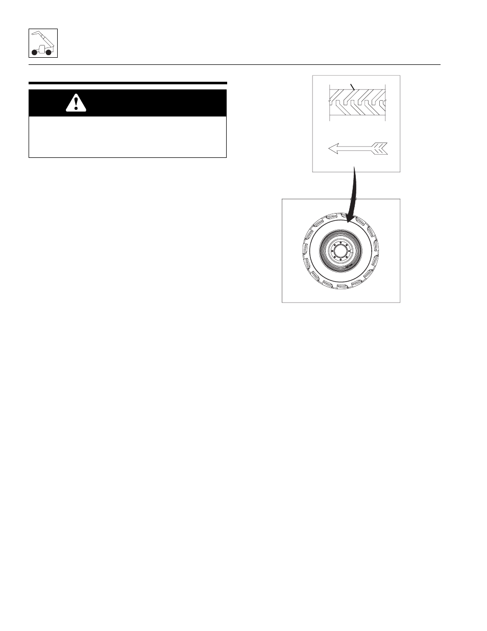
on the wheel, the tire must be mounted on the wheel
respective of the directional tread pattern of the tire; this
produces a left or right tire and wheel assembly.
The wheel and tire assemblies must be installed with the
directional tread pattern “arrows” (4) facing in the
direction of forward travel.
5.5.1
Removing Wheel and Tire Assembly
from Machine
1. Park the machine on a firm, level surface, fully
retract the boom, lower the boom, place the
transmission control lever in (N) NEUTRAL, engage
the park brake and shut the engine OFF.
2. Place an Do Not Operate Tag on both the ignition
key switch and steering wheel, stating that the
machine should not be operated.
3. Loosen but DO NOT remove the lug nuts on the
wheel and tire assembly to be removed.
4. Place a suitable jack under the axle pad closest to
the wheel being removed. Raise the machine and
position a suitable support beneath the axle. Allow
sufficient room to lower the machine onto the
support and to remove the wheel and tire assembly.
5. Lower the machine onto the support.
6. Remove lug nuts and lug washers in an alternating
pattern.
7. Remove the wheel and tire assembly from the
machine.
WARNING
Risk of death or serious personal injury. Mismatched
tire sizes, ply ratings or mixing of tire types (radial tires
with bias-ply tires) may compromise machine stability
and could cause machine to tip over.
MAH0890
4