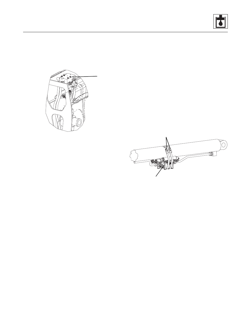
4 auxiliary valve, 5 telescope valve, Auxiliary valve – JLG G12-55A AccuPlace Service Manual User Manual
Page 107: Telescope valve
8.17
G10-55A & G12-55A AccuPlace
Hydraulic System
Note: This will ensure that there is approximately a 325
psi (22 bar) margin between the valve LS and pump
output.
8.8.4
Auxiliary Valve
a. Auxiliary Valve Removal
1. Remove any attachment from the boom. Park the
machine on a firm, level surface, level the machine,
fully retract the boom, lower the boom, place the
transmission control lever in (N) NEUTRAL, engage
the park brake and shut the engine OFF.
2. Place a Do Not Operate Tag on both the ignition key
switch and the steering wheel, stating that the
machine should not be operated.
3. Open the engine cover. Allow the system fluids to
cool.
4. Disconnect the battery negative (-) cable from the
battery negative (-) terminal.
5. Remove the protective cover from the boomhead.
6. Thoroughly clean the valve and surrounding area,
including all hoses and fittings before proceeding.
7. Label, disconnect and cap the hydraulic hoses
attached to the auxiliary valve (8). Cap all fittings to
prevent dirt & debris from entering the hydraulic
system.
8. Label and disconnect the electrical connectors from
the auxiliary valve.
9. Remove the hardware securing the auxiliary valve to
the boomhead.
b. Auxiliary Valve Installation
1. Install the auxiliary valve to the boomhead with the
previously used hardware.
2. Connect the previously labeled electrical connectors
to the auxiliary valve.
3. Uncap and connect the previously labeled hydraulic
hoses to their appropriate locations.
4. Connect the battery negative (-) cable to the battery
negative (-) terminal.
5. Before starting the machine, check fluid level of the
hydraulic fluid reservoir and if necessary fill to full
mark with Mobilfluid 424
®
(ISO 46).
6. Start the machine and run at low idle for about one
minute. Test the functions of the auxiliary valve.
7. Inspect for leaks and check level of hydraulic fluid in
reservoir. Add hydraulic fluid if needed. Shut the
engine OFF.
8. Install the protective cover on the boomhead.
9. Close and secure the engine cover.
8.8.5
Telescope Valve
a. Telescope Valve Removal
1. Park the machine on a firm, level surface, level the
machine, fully retract the boom, lower the boom,
place the transmission control lever in (N) NEUTRAL,
engage the park brake and shut the engine OFF.
2. Place a Do Not Operate Tag on both the ignition key
switch and the steering wheel, stating that the
machine should not be operated.
3. Open the engine cover. Allow the system fluids to
cool.
4. Disconnect the battery negative (-) cable from the
battery negative (-) terminal.
5. Label, disconnect and cap the hydraulic hoses
attached to the telescope valve (9). Cap all fittings to
prevent dirt & debris from entering the hydraulic
system.
6. Label and disconnect the electrical connectors from
the telescope valve.
7. Support the telescope valve and remove the bolts on
the clamps (10) securing the telescope valve to the
extend cylinder.
MAP0250
8
MAP0710
10
9