7 engine start circuit, 1 starter, Engine start circuit – JLG G12-55A AccuPlace Service Manual User Manual
Page 141: Starter
9.23
G10-55A & G12-55A AccuPlace
Electrical System
9.7
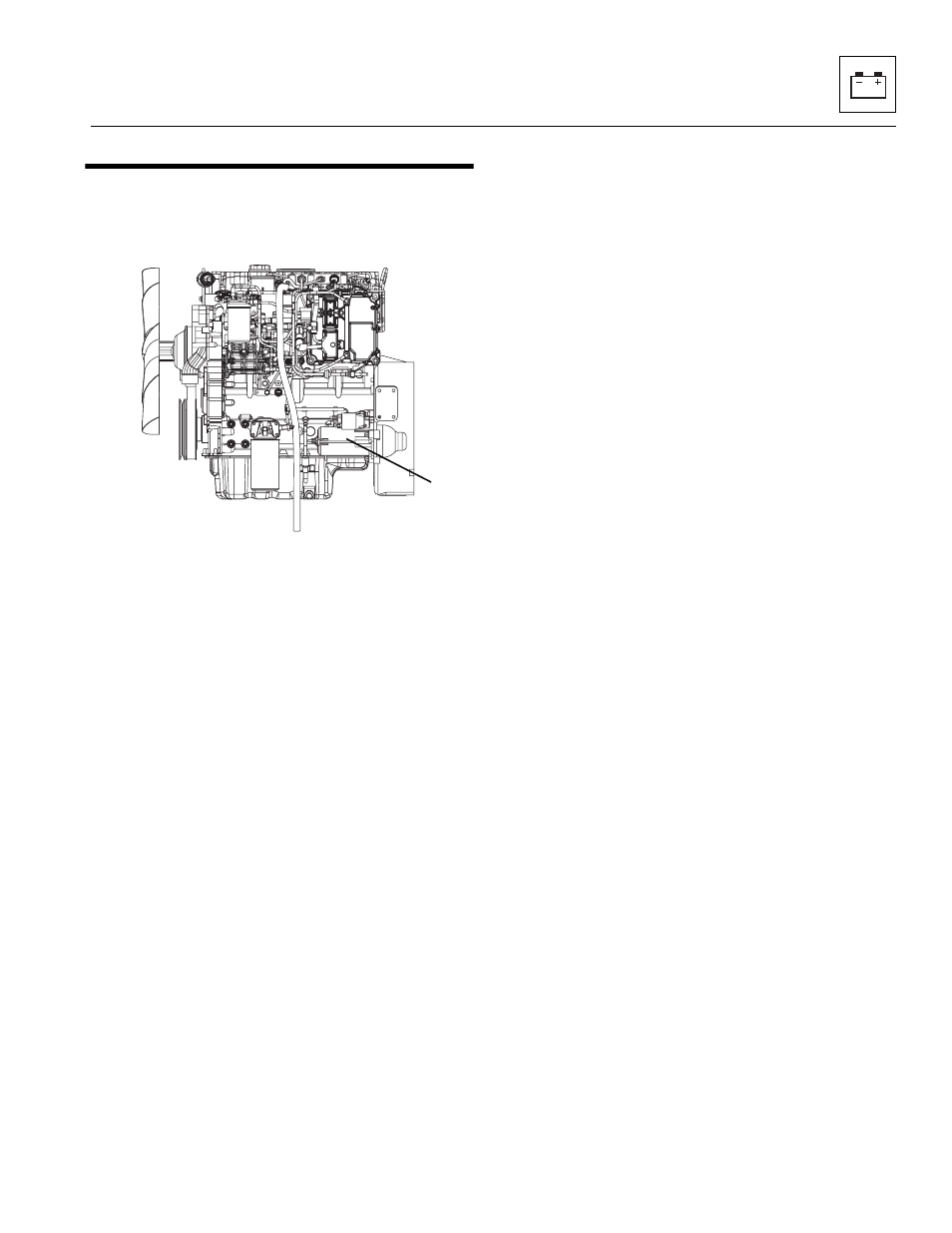
ENGINE START CIRCUIT
9.7.1
Starter
The starter (1) is located on the left side of the engine.
a. Testing the Starter on the Engine
If the starter does not engage when the ignition key
switch is turned, check the following:
1. The main fuse may be blown, requiring replacement.
Check for the cause of the blown fuse.
2. There may be a defect in the ignition key switch,
ignition wiring or starter solenoid.
3. Check battery condition. Clean the battery posts and
the connectors at each end of the battery cables.
4. Check for broken wiring and damaged insulation on
the wiring. Replace all broken or damaged wiring.
5. Check all connections at the starter solenoid, key
switch and wiring harness plugs. Clean and tighten
all connections.
6. If the starter still does not operate after these checks
have been performed, check the starting circuit.
b. Starter Circuit Checks
1. Check wires and connections for looseness,
corrosion, damage, etc.
2. If a “whirring” noise is heard but the engine does not
turn over, the starter is spinning but not engaging the
flywheel. The starter drive or solenoid that pushes
the drive forward to engage the flywheel may be
defective. Missing or damaged teeth on the flywheel
can also prevent the starter from cranking the
engine.
3. If the starter only “clicks” it may indicate that the
battery is discharged, or that there is a loose or
corroded battery cable connection. Check the
battery state of charge and battery condition first,
then check the cables and cable connections.
4. For additional information on the starting circuit, refer
to Section 9.6, “Electrical System Schematics And
Diagrams.”
c. Starter Removal
Remove the starter only if it fails. To remove the starter:
1. Open the engine cover.
2. Disconnect the battery negative (-) cable at the
battery negative (-) terminal.
3. Remove the wires from the solenoid stud. Remove
the positive (+) battery cable from the starter. Label
and disconnect the wire from the starter solenoid
housing stud. Record how the wires are installed to
ensure correct installation later.
4. Loosen, but DO NOT remove, the three fasteners
securing the starter to the flywheel housing. Support
the starter securely, as it is relatively heavy and will
fall if not supported.
5. Support the starter and remove the fasteners
securing the starter to the engine. Remove the
negative (-) ground cable from its starter mounting
bolt.
6. Remove the starter from the machine.
d. Starter Installation
1. Position the starter in its mounting opening on the
flywheel housing. Position the ground cable over the
correct starter mounting bolt. Secure the starter with
the three fasteners.
2. Connect the positive (+) battery cable to the upper
solenoid stud. Install the wires to the upper solenoid
stud, and secure with lock washer and nut.
3. Connect the wire to the solenoid mounting stud.
4. Connect the battery negative (-) cable to the battery
negative (-) terminal.
5. Close and secure the engine cover.
MY1850
1