10 cab heater and fan, 1 cab heater controls, Cab heater and fan – JLG G12-55A AccuPlace Service Manual User Manual
Page 144: Cab heater controls
Electrical System
9.26
G10-55A & G12-55A AccuPlace
3. Open the engine cover. Allow the system fluids to
cool.
4. Disconnect the battery negative (-) cable from the
battery negative (-) terminal.
5. Remove the nuts and the lock washers from the
washer mounting bolts.
6. Pull the washer reservoir out and away from the
mounting bracket.
7. Rotate the washer reservoir, label and remove the
cab harness connectors from the washer reservoir
connectors.
8. Remove the windshield washer hoses from the
reservoir.
b. Disassembly
DO NOT disassemble the pump. The pump is not
serviceable. Replace pump if found to be defective.
c. Installation and Testing
1. Connect the windshield washer hoses to the
reservoir.
2. Connect the cab wiring harness connectors to the
reservoir connectors.
3. Install the reservoir tank onto the mounting bracket.
4. Install the lock washers and nuts and secure.
5. Fill the washer fluid reservoir with washer fluid.
6. Connect the battery negative (-) cable to the battery
negative (-) terminal.
7. Turn the ignition key switch to the RUN position and
press the washer switch. Verify that fluid is sprayed
on both the windshield and rear glass.
9.10
CAB HEATER AND FAN
9.10.1
Cab Heater Controls
Note: If the suspect component is found to be within the
heater box, the heater box must be removed as a
complete unit and replaced.
a. Cab Heater Controls Removal
1. Park the machine on a firm, level surface, level the
machine, fully retract the boom, lower the boom,
place the transmission control lever in
(N) NEUTRAL, engage the park brake and shut the
engine OFF.
2. Place a Do Not Operate Tag on both the ignition key
switch and the steering wheel, stating that the
machine should not be operated.
3. Open the engine cover. Allow the system fluids to
cool.
4. Disconnect the battery negative (-) cable from the
battery negative (-) terminal.
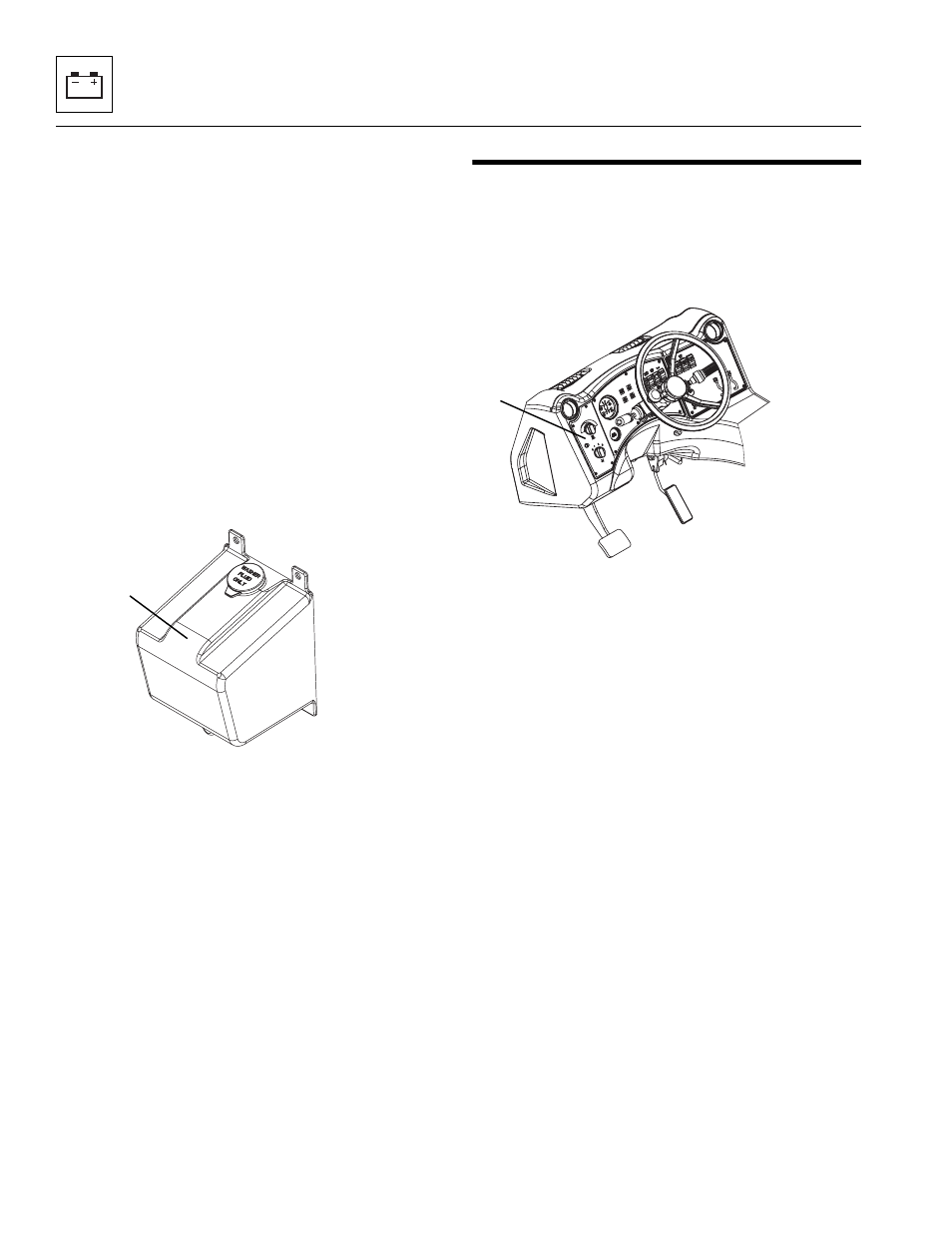
5. Remove the screws securing the left cab dash panel
(5).
6. Pull out the panel to gain access to the heater
control electrical connections. Disconnect the
harnesses.
7. Remove the heater control knobs.
8. Remove the necessary hardware securing the
heater control from the dash panel. Remove the
control from the panel.
b. Disassembly
DO NOT disassemble the cab heater and fan controls.
The controls are not serviceable. Replace controls if
found to be defective.
MY1220
4
MAP0590
5