6 windshield wiper assembly, 7 heater/defroster system (if equipped), Windshield wiper assembly – JLG G12-55A AccuPlace Service Manual User Manual
Page 50: Heater/defroster system (if equipped)
Cab and Covers
4.6
G10-55A & G12-55A AccuPlace
b. Boom Joystick Assembly Installation
1. Connect the electrical harness connector to the
joystick.
2. Ensure the rubber sleeve at the base of the joystick
is secured over all four corners of the base of the
joystick. If necessary, carefully pull the rubber sleeve
over the four corners.
3. Place the joystick into the mount and install the bolts
securing the boom joystick to the cab. Ensure the
rubber sleeve on the joystick stays in place when
tightening the bolts.
4. Place the plastic right hand panel into position and
secure with bolts. Ensure the rubber sleeve on the
joystick remains under the panel.
5. Connect the battery negative (-) cable to the battery
negative (-) terminal.
6. Test the joystick functions.
7. Close and secure the engine cover.
4.3.5
Frame Level, Auxiliary Hydraulic and
Outrigger Joysticks
a. Joystick Removal
1. Park the machine on a firm, level surface, level the
machine, fully retract the boom, lower the boom,
place the travel select lever in the (N) NEUTRAL
position, engage the parking brake and turn the
engine OFF.
2. Place a Do Not Operate Tag on both the ignition key
switch and steering wheel, stating that the machine
should not be operated.
3. Disconnect the battery negative (-) cable at the
battery negative (-) terminal.
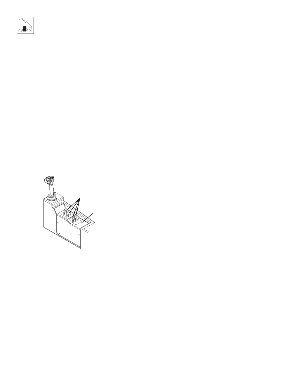
4. Remove the screws securing the RH panel (9) to the
cab. Remove the RH panel.
5. Label and disconnect the electrical connector to the
joystick (10).
6. Remove any hardware securing the joystick to the
dash panel.
7. Remove the joystick.
b. Joystick Installation
1. Install the joystick to the RH panel.
2. Connect the previously labeled electrical connector
to the joystick.
3. Install the RH panel to its original position with the
previously used hardware.
4. Connect the battery negative (-) cable to the battery
negative (-) terminal.
5. Test the complete range of the joystick functions:
6. Close and secure the engine cover.
4.3.6
Windshield Wiper Assembly
Refer to Section 9.9, “Window Wiper/Washer Windshield
Wiper Motor,” for removal and installation information.
4.3.7
Heater/Defroster System (If equipped)
a. Heater Assembly Removal
1. Park the machine on a firm, level surface, level the
machine, fully retract the boom, lower the boom,
place the travel select lever in the (N) NEUTRAL
position, engage the park brake and shut the engine
OFF.
2. Place a Do Not Operate Tag on both the ignition key
switch and the steering wheel, stating that the
machine should not be operated.
3. Open the engine cover. Allow the system fluids to
cool.
4. Disconnect the battery negative (-) cable at the
battery negative (-) terminal.
5. Place a suitable container beneath the radiator.
Slowly turn the radiator cap to the first stop, and
allow any pressure to escape. Remove the radiator
cap.
6. Place a funnel at the base of the radiator to channel
the drained coolant into the container. Loosen the
drain petcock and allow the coolant to drain.
7. Transfer the coolant to a container with a cover, and
label as “Used Antifreeze.” Dispose of the used
coolant at an approved recycling facility.
8. Tighten the radiator drain petcock.
MY2770
9
10